multi- stage instruction is relative value, which is the percentage of relative maximum frequency F0.07. The
positive or negative of the parameter determines the running direction, if it is negative, it means the inverter
runs in the opposite direction.
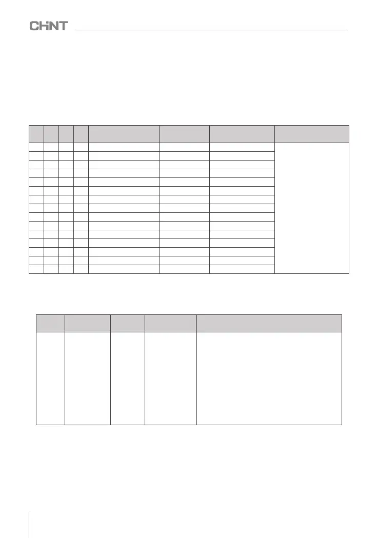
4 X terminals are selected as the signal input terminals K1~K4 for multi-segment frequency designation,
and they are sequentially formed into 4-bit binary numbers: 1 means that the setting function of the X terminal
is valid, and 0 means that the setting function of the X terminal is invalid.
According to the state, it can be combined into 15 states, and these 15 states correspond to 15 command
setting values. The details are shown in the following table:
K4
K3
K2
K1
command setting
Corresponding
parameters
Predetermined
area
Remark
0
0
0
0
0
0
0
0
1
1
1
1
Multi-band frequency 1
FA.31
( -100.0 ~ +100.0 )%
100 % is the percentage
relative to the maximum
frequency (F 0.0 7), the
positive or negative of the
parameter determines the
running direction, and the
negative value means
running in the opposite
direction
0
0
0
0
1
1
1
1
0
0
0
0
Multi-band frequency 2
FA.31
( -100.0 ~ +100.0 )%
0
0
0
0
1
1
1
1
1
1
1
1
Multi-band frequency 3
FA.33
( -100.0 ~ +100.0 )%
0
1
1
1
1
1
1
1
1
1
1
1
1
1
1
1
1
0
0
0
0
0
0
0
Multi-band frequency 4
FA.34
( -100.0 ~ +100.0 )%
Multi-band frequency 5
FA.35
( -100.0 ~ +100.0 )%
Multi-band frequency 6
FA.36
( -100.0 ~ +100.0 )%
Multi-band frequency 7
FA.37
( -100.0 ~ +100.0 )%
Multi-band frequency 8
FA.38
( -100.0 ~ +100.0 )%
Multi-band frequency 9
FA.39
( -100.0 ~ +100.0 )%
Multi-band frequency 10
FA.40
( -100.0 ~ +100.0 )%
Multi-band frequency 11
FA.41
( -100.0 ~ +100.0 )%
Multi-band frequency 12
FA.42
( -100.0 ~ +100.0 )%
Multi-band frequency 13
FA.43
( -100.0 ~ +100.0 )%
Multi-band frequency 14
FA.44
( -100.0 ~ +100.0 )%
Multi-band frequency 15
FA.45
( -100.0 ~ +100.0 )%
8.2.5 Set main frequency through simple PLC
When the simple PLC is used as the main frequency, set FA.00 to select the operation mode of the simple
PLC, whether to remember the operating stage and operating frequency of the PLC before power failure after
power failure or shutdown:
When the operating frequency of the simple PLC is selected to be given by the multi-segment frequency
N (the unit digit of FA.01 is 0), it is necessary to set the parameter FA.31~FA.45, FA.01~FA.30 set the running
time, acceleration and deceleration time and running direction of each segment;
function
code
name
default
value
Predetermined
area
Parameter Description
FA.00
Simple PLC
operation
mode selection
0x0000
0x0000 ~ 0x1112
Everyone: PLC operation mode
0: Stop after a single cycle
1: Keep the final value after a single loop
2: continuous loop
Tens place: downtime storage
0: do not store
1: Store downtime phase, frequency
Hundreds place: power-off storage
0: do not store
1: Store power-off time stage, frequency
Thousands: stage time unit selection
0: seconds
1 point
040
NVF2G-S Series Inverter User's Guide
 Loading...