Frequency Hz
Output
voltage
(valid)
braking
Time t
Time t
braking
time
Run
order
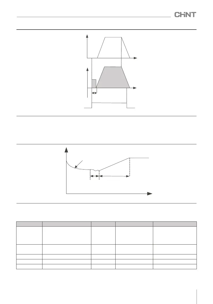
● Speed tracking (including direction discrimination) restart
Set F1.00=2, the inverter will start after speed tracking (the inverter first judges the speed and direction of
the motor, and then starts with the tracked motor frequency). It is suitable for driving large inertial mechanical
loads. If the load motor is still running by inertia when the inverter starts running, the speed tracking and
restarting can avoid the occurrence of overcurrent at startup.
Figure 8-3-2 Sequence diagram of braking first and then starting
Output
frequency
Motor speed
Motor speed search time
Time t
Acc.
8.3.2 Shutdown mode
The frequency converter has three stop modes, which are deceleration stop, free stop and deceleration stop
+ DC braking. Set parameter F1.05 to select the stop mode of the inverter.
Figure 8 -3-3 Sequence diagram of speed tracking restart
● Deceleration stop
Set F1.05=0, the inverter decelerates to stop. After the stop command is valid, the inverter reduces the
output frequency according to the deceleration time, and stops after the frequency drops to 0.
function code
name
default value
Predetermined area
Parameter Description
F1.05
Shutdown mode
0 0~2
F1.06
Start frequency of DC braking
at stop
0.00Hz 0.00Hz~F0.07
--
F1.07
Stop DC braking waiting time
0.0s
(0.0~100.0)s
--
F1.08
Stop DC brake current
0.0%
(0.0~100.0)%
100% (inverter rated current)
F1.09
Stop DC braking time
0.0s
(0.0~100.0)s
--
0: decelerate to stop
1: free stop
2: Deceleration to stop +
DC braking
047
NVF2G-S Series Inverter User's Guide
 Loading...