run command is canceled once, and the inverter will respond only after the run command becomes valid again.
8.9.2 Motor overload protection
● Motor overload protection gain
In order to effectively protect the motor under different loads, it is necessary to adjust the motor overload
protection gain according to the current output overload capacity
FE.01 is set, the motor overload protection is an inverse time curve.
FE.00
Motor overload
protection selection
1
0~1
0: disabled
1: allow
FE.01
Motor overload
protection gain
1.00
0.20 ~ 10.00
--
FE.02
Motor overload
warning function
00
0~1
0: invalid
1: valid
F E.03
Motor overload
warning level
80%
(20 ~ 200)%
--
function code
name
default value
Predetermined area
Parameter Description
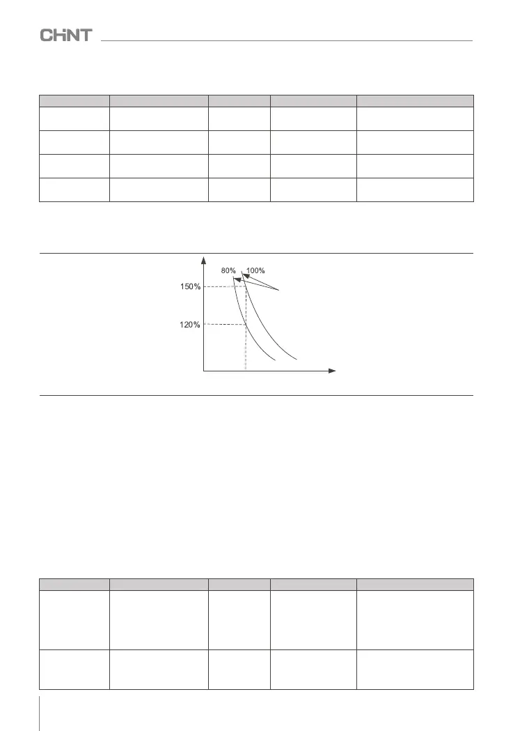
Figure 8-9-1 Schematic diagram of motor overload inverse time curve
Current
Motor overload
protection factor
10 min
Time t
Overload protection gain FE.01 is set to 1.00 , the default inverse time characteristic of the motor overload
protection is: the motor overload will be reported after 10 minutes of continuous operation at 150% of the rated
current of the motor; the motor overload will be reported after 80 minutes of continuous operation at 110% of
the rated current of the motor .
● Motor overload warning
The motor overload warning function is used to output a warning signal to the control system through DO
before the motor overload fault protection. The early warning coefficient is used to determine the degree of
early warning before the motor overload protection, the larger the value, the smaller the early warning amount.
When the accumulative output current of the inverter is greater than the product of the overload time (the
accumulative value of the inverse time-limit curve of the motor overload protection) and the FE.03 motor
overload pre-alarm level, the multi-function digital terminal DO of the inverter outputs a valid signal of the
motor overload pre-alarm.
In special cases, when the motor overload warning level FE.03 is set to 100%, the early warning advance
amount is 0, and at this time the pre-alarm and overload protection occur simultaneously.
8.9.3 Phase loss protection
FE.24
Input phase loss detection
selection
1
0~2
function code
name
default value
Predetermined area
Parameter Description
0: output phase loss software
does not detect
1: Output phase loss software
detection
FE.25
Output phase loss
detection selection
1
0~2
0: Input phase loss hardware
detection
1: Input phase loss software
detection
2: Input phase loss software and
hardware are not detected
054
NVF2G-S Series Inverter User's Guide
 Loading...