LCR Meter 11021 / 11021-L User’s Manual
5-2
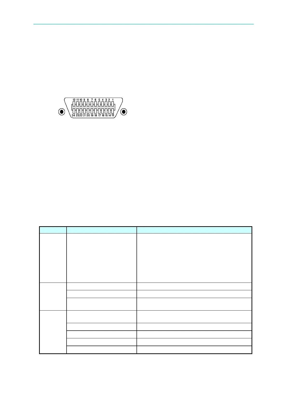
5.2.4 IEEE-488 Interface Connector
z Below shows the connector pin assignment:
1 DIO1 13 DIO5
2 DIO2 14 DIO6
3 DIO3 15 DIO7
4 DIO4 16 DIO8
5 EOI 17 REN
6 DAV 18 GND
7 NRFD 19 GND
8 NDAC 20 GND
9 IFC 21 GND
10 SRQ 22 GND
11 ATN 23 GND
12 SHIELD 24 GND
z Meter side connector:
DDK 57 LE-20240 or equivalent.
z Cable side connector.
DDK 57-10240 or equivalent.
5.2.5 Signal Cable of IEEE-488 Interface
z The interface is composed of the data, the handshake and the control ports as shown in
the table below:
Port Signal Cable of Port Description
Data Port
DIO1 (Data Input/Output 1)
DIO2 (Data Input/Output 2)
DIO3 (Data Input/Output 3)
DIO4 (Data Input/Output 4)
DIO5 (Data Input/Output 5)
DIO6 (Data Input/Output 6)
DIO7 (Data Input/Output 7)
DIO8 (Data Input/Output 8)
Besides data input, it is also used for interface
and device message input/output.
DAV (Data Valid) Indicate that the data on the data port are valid.
NRFD (Not Ready For Data) Indicate that the listener is ready to receive.
Handshak
e Port
NDAC (Not Data Accepted)
Indicate that the listener has finished the data
reception.
ATN (Attention)
Indicate the signal on the data port carries data
or message of an interface or device.
REN (Remote Enable)
Switch between remote and local control mode.
IFC (Interface Clear) Used to reset the interface.
SRQ (Service Request) Signal sent by talker to call the controller.
Control
Port
EOI (End of Identification) Indicate end of data.