Description of Handler Interface
7-1
7. Description of Handler Interface
The BINNING and COMPARE in 11021/11021-L are connected to external unit by Handler
interface. The connector is 24-pin, and its pin assignment is described as below.
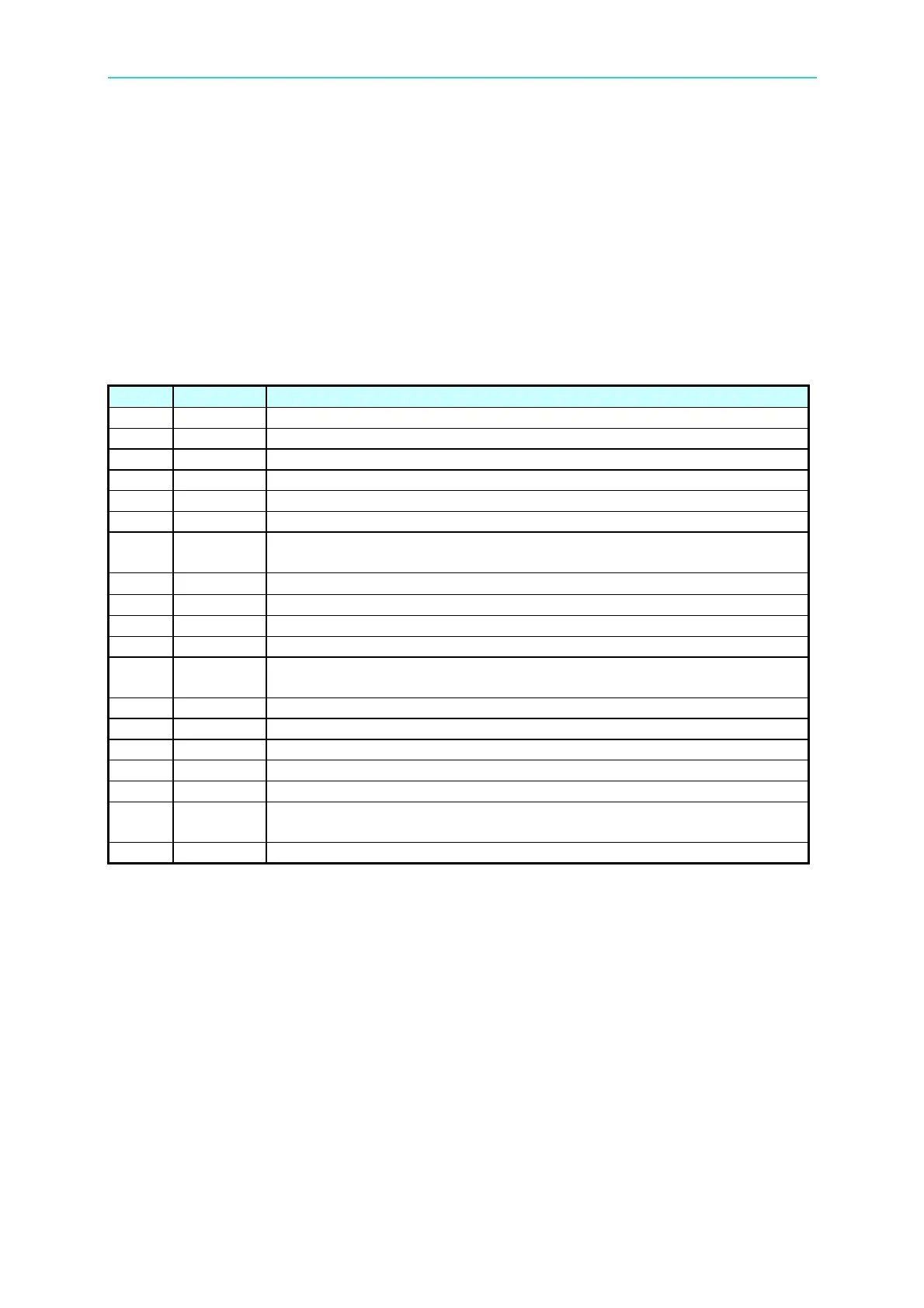
7.1 Description of Handler Interface Pins for
BINNING
Pin Name Description
1 /EXT External trigger.
2 X N.C
3, 20 BIN 7 BIN 7, the primary parameter test value is within the set BIN 7 range.
4, 24 BIN 8 BIN 8, the primary parameter test value is within the set BIN 8 range.
5-7 GND Ground the external DC power source.
8 COMMON The internal power grounding terminal, connect to earth.
9, 13 BIN OUT
BIN OUT, the primary parameter test value is not within the
specifications set.
10 VEXT
External DC voltage, the acceptable voltage range is 5V
∼ 24V.
11 VINT Internal DC voltage +5V
12 X N.C
14 BIN 5 BIN 5, the primary parameter test value is within the set BIN 5 range.
15 BIN 0
BIN 0, the secondary parameter test value exceeds the set upper,
lower value
16 BIN 6 BIN 6, the primary parameter test value is within the set BIN 6 range.
17 BIN 1 BIN 1, the primary parameter test value is within the set BIN 1 range.
18 /EOT End of test.
19 BIN 2 BIN 2, the primary parameter test value is within the set BIN 2 range.
21 BIN 3 BIN 3, the primary parameter test value is within the set BIN 3 range.
22 /ACQ
End of the analog sampling. It is able to move the next DUT to the
11021/11021-L test terminal.
23 BIN 4 BIN 4, the primary parameter test value is within the set BIN 4 range.