Programmable DC Electronic Load 6310 Series Operation & Programming Manual
Master
Frame
Slave
Frame
Slave
Frame
Slave
Frame
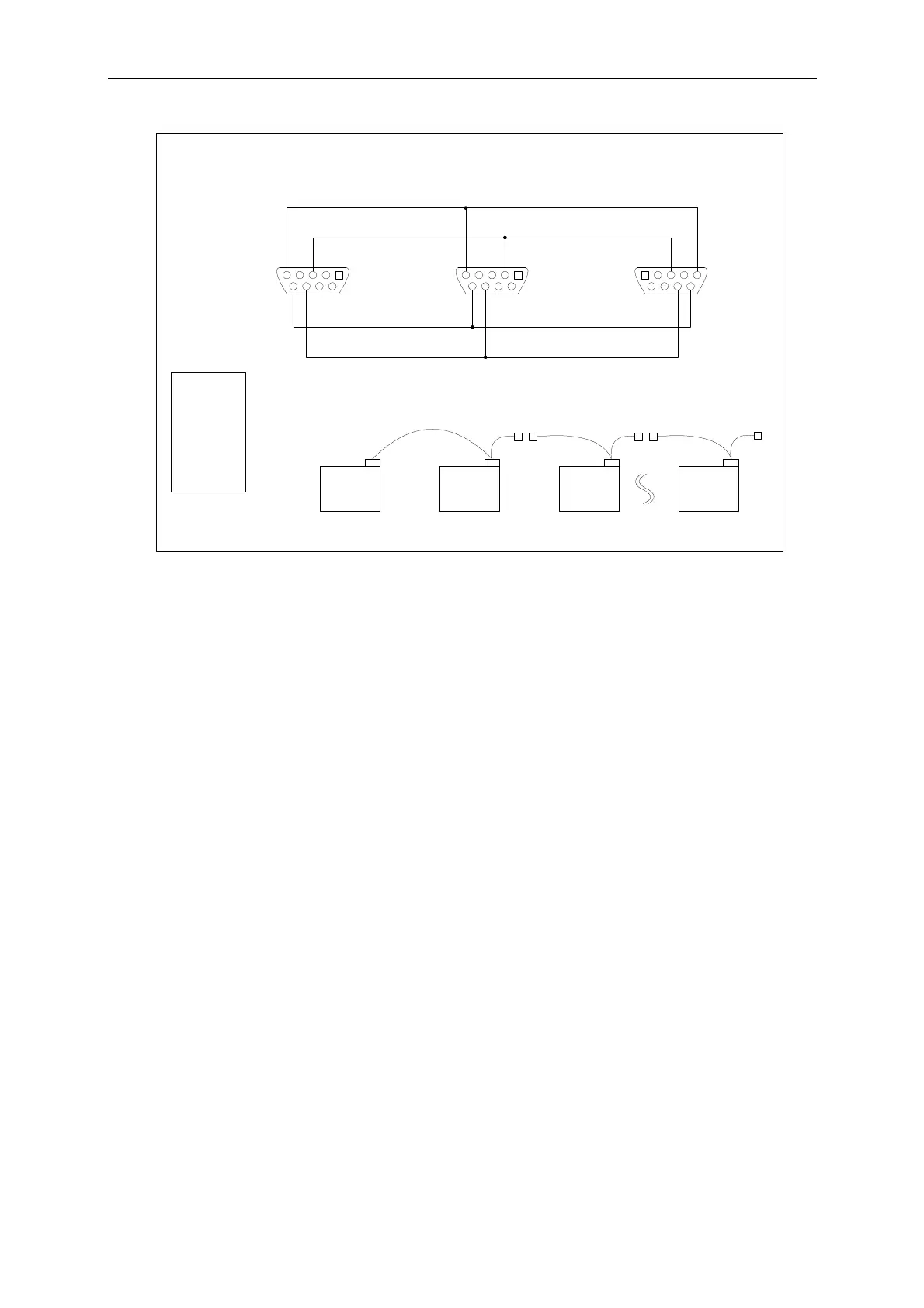
RS232 Hardware Connection Diagram
1. +5V
2. Rx
3. Tx
4. DTR
5. GND
6. DSR
7.
8. MISO
9. MOSI
15
69
15
69
1
6
5
9
Female
Connector
Master Frame
Female
Connector
Slave Frame
Male
Connector
Figure 3-10 RS232 Hardware Connection Diagram
Test: 6334 mainframe x2 + 63303 load module x2
Condition: Set 12 V parallel two 63303 loads sync loading
63303 Load no.1: CC mode A: 2A ,B:14A ;T1:100uS; T2:100uS ; Slew rate sets to 0.5A/uS.
63303 Load no.2: CC mode A: 2A, B:14A ;T1:100uS; T2:100uS ; Slew rate sets to 0.5A/uS.
3-14

 Loading...
