Operation
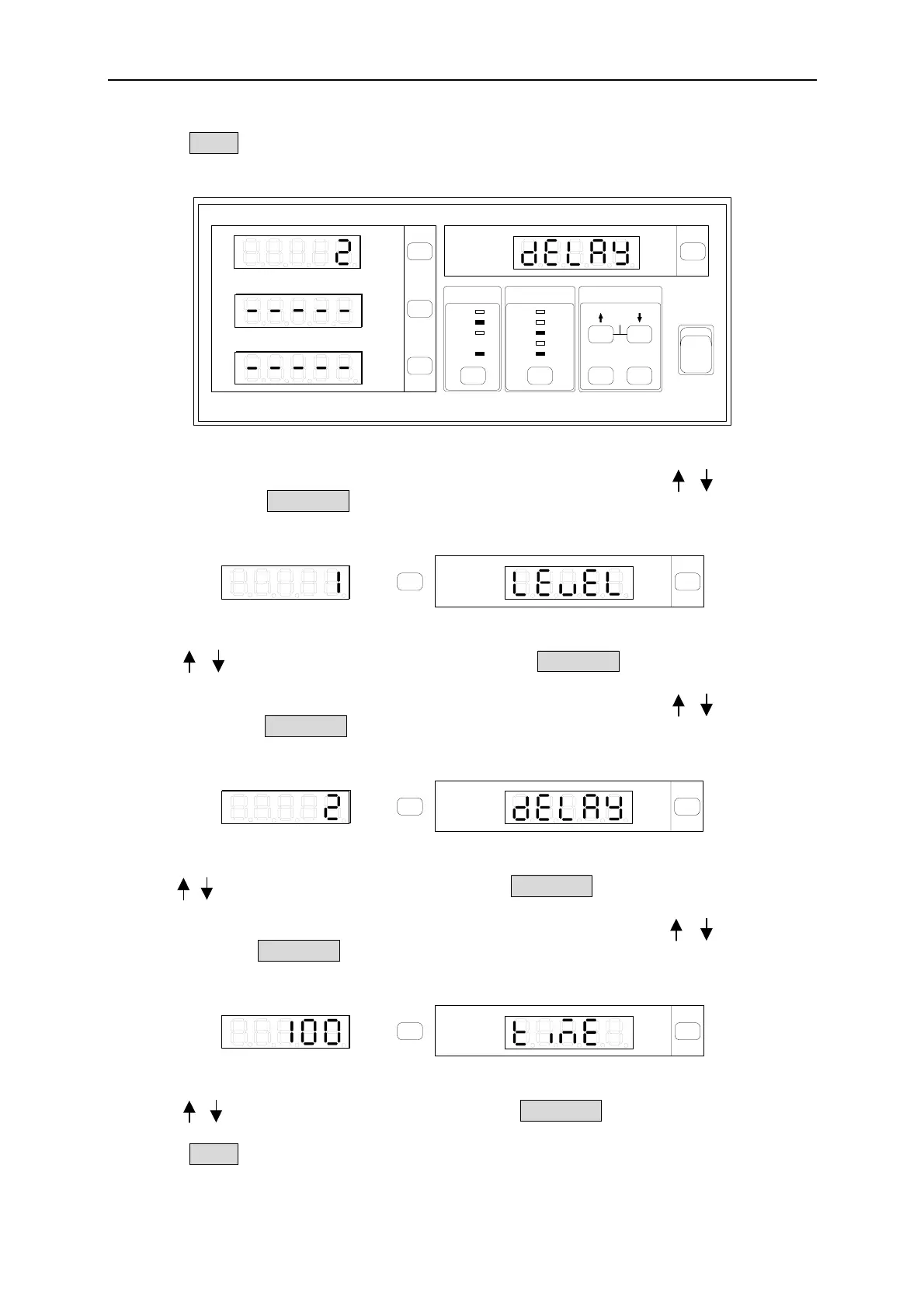
1. Press Setup to select Is/Trig and the indicator of Is/Trig is on. Figure 4-25 shows the
setting of Is/Trig.
20
8
2
0.2
AUTO AUTOAUTO
150
300
500
VOLTAGE
CURRENT
SHUNT
2
0.4
0.1
0.01
LH
SYSTEM
Cali
Setup
Trig /
Enter
ON
OFF
I
O
GO/NG
PASS
Shunt
Limit
Meas
RMT
FAIL
Is/Trig
PF F
E
CF
THDv
THD
V
Vpk+
Vpk-
mA
I
Ipk+
Ipk-
Is
W
PF
VA
VAR
Chroma
DIGITAL POWER METER
MODEL
66202
k
Figure 4-25 Setting Is/Trig
2. In the special measurement display a blinking pattern will appear. Use , to select
Level and press Enter/Trig to save the setting and go to trigger Level (ampere) selection
display as Figure 4-26 shows.
GO/NG
PASS
Shunt
Limit
Meas
RMT
FAIL
Is/Trig
PF F
E
CF
THDv
THD
V
Vpk+
Vpk-
k
Figure 4-26 Setting LEVEL and Current
3. Use , to set the Level (ampere) and then press Enter/Trig to save the setting and go
to the display of Step 2.
4. In the special measurement display a blinking pattern will appear. Use , to select
delay and press Enter/Trig to save the setting and go to Delay time (ms) selection
display as Figure 4-27 shows.
GO/NG
PASS
Shunt
Limit
Meas
RMT
FAIL
Is/Trig
PF F
E
CF
THDv
THD
V
Vpk+
Vpk-
k
Figure 4-27 Setting DELAY and Time Length
5. Use , to set the time(second) and then press Enter/Trig to save the setting and go to
the display of Step 2.
6. In the special measurement display a blinking pattern will appear. Use , to select
time and press Enter/Trig to save the setting and go to measurement Time (ms) selection
display as Figure 4-28 shows.
GO/NG
PASS
Shunt
Limit
Meas
RMT
FAIL
Is/Trig
PF F
E
CF
THDv
THD
V
Vpk+
Vpk-
k
Figure 4-28 Setting TIME and Time Length
7. Use , to set the time(second) and then press Enter/Trig to save the setting and go
to the display of Step 2.
8. Press Setup to exit the function setting display.
4-17
 Loading...


