2-18 Installation
5150 Service Aggregation Switch Hardware Installation and Start-up Manual
009-3222-001 Standard Revision H
Copyright
©
2012-2015 Ciena
®
Corporation July 2015
Procedure 2-4
To Install Supplemental Ground
The ground lug and ground wire are customer supplied. The specifications are
provided in “Grounding” on page 2-5.
The supplemental ground connection is made on the rear of the chassis. If you
will not have access to the rear of the chassis after the system is mounted in
the frame, install the supplemental ground connection before you mount the
system.
Step Action
1 Route the supplemental ground cable through the cabinet or installation site.
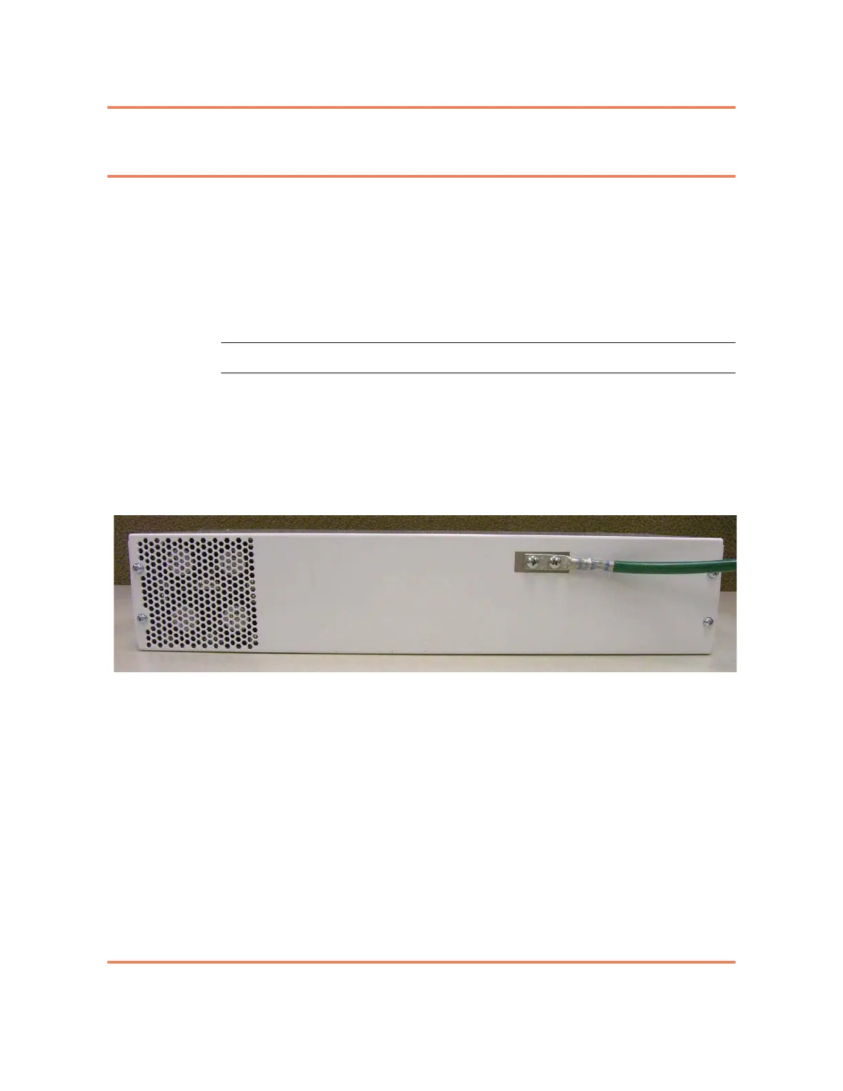
2 Using a Phillips screwdriver and the two screws (supplied), connect a copper
conductor ground wire to the ground connectors on the right of the rear of the
chassis. Figure 2-2 shows the grounding lug attached to the chassis with the
supplied screws.
Figure 2-2
Installed grounding lug
3 Connect the other end of the grounding wire to supplemental ground in
accordance with local and national regulations and safety guidelines, and the
grounding procedures used by your company.
4 Using an appropriate Digital Milli-Ohm meter, verify that the DC resistance
between the chassis and the supplemental ground source is less than 25
milliohms.
You have mounted and grounded the 5150. You are now ready to
proceed with one of the following:
• “To Install the 10 Gigabit Option Modules” on page 2-19 (these modules
are optional)
• “To Install an AC Power Supply” on page 2-20
• “To Install a DC Power Supply” on page 2-22