8-8 Mounting Options
5150 Service Aggregation Switch Hardware Installation and Start-up Manual
009-3222-001 Standard Revision H
Copyright
©
2012-2015 Ciena
®
Corporation July 2015
Procedure 8-3
Installing the 23” Frame Mount Bracket - 2 RU
Step Action
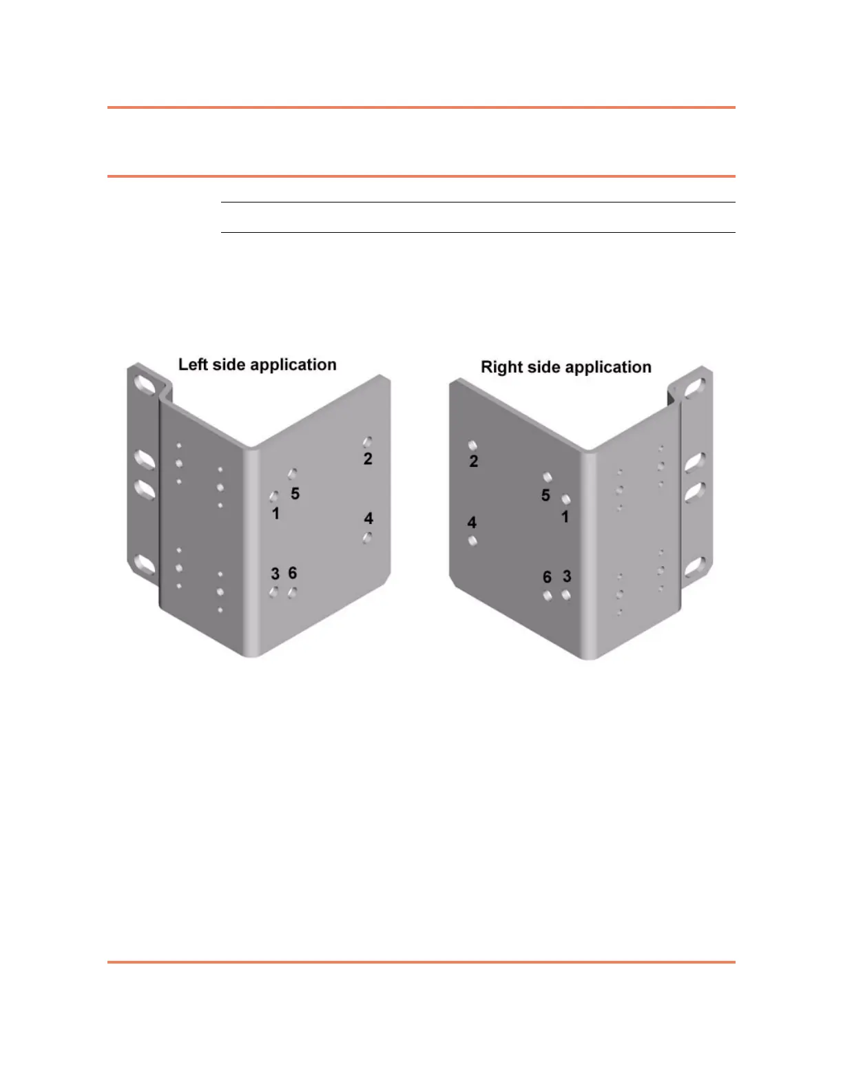
1 Align the holes of the mounting bracket with the holes on the side of the unit
(see Figure 8-5) as follows:
• install screws in holes 1, 2, 3, and 4
Figure 8-5
Mounting bracket, with holes labeled
2 Repeat step 1 to install the second bracket.
3 Position the chassis in place in the frame.
4 Install four customer supplied screws in the slots on both the left and right
brackets. Use local practices to determine screw placement to attach the
bracket to the frame.
5 Tighten all screws to ensure they make a firm connection between the
bracket and the frame.
6 Install the cable support on the mounting brackets using either the Inner or
Outer screw position and the four longer 8-32 screws provided in the kit. Two
screws will be used per bracket. Figure 8-5 shows the Cable Supports
installed on the mounting bracket. Figure 8-6 on page 8-9 shows the Inner
and Outer mounting holes available on the bracket.