8-8 Mounting Options
5160 Service Aggregation Switch Hardware Installation and Start-up Manual
009-3207-001 Standard Revision A
Copyright
©
2013 Ciena
®
Corporation September 2013
Procedure 8-2
Installing the 19” Frame Mount Bracket - 1 RU
Step Action
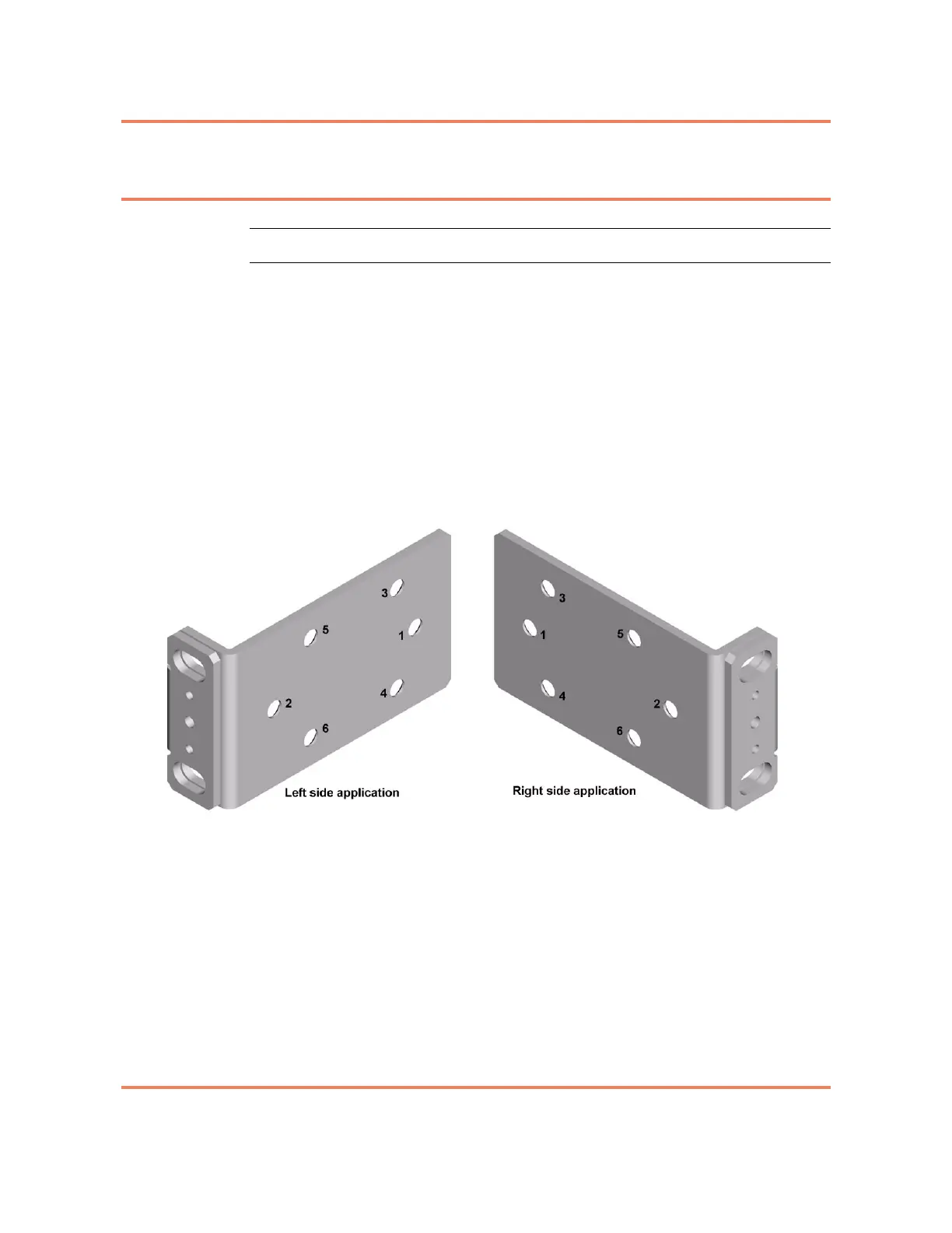
1 Align the holes of the mounting bracket with the holes on the side of the unit
(see Figure 8-5) as follows:
• 3930, 3932, 3940, 3960, 5142 and 5160 — install screws in holes 1
and 2.
• 3920 — install screws in holes 5 and 6.
Note: When mounting a 3920, install the screws in the set of holes on the
side of the chassis that is located closest to the middle of the chassis.
Note: When correctly installed, the mounting flange will be recessed
approximately 2 inches from the front faceplate of the chassis.
Figure 8-5
Mounting bracket, with holes labeled
2 Repeat step 1 to install the second bracket.
3 Position the chassis in place in the frame.
4 Install four customer supplied screws in the slots on both the left and right
brackets.
5 Tighten all screws to ensure they make a firm connection between the
bracket and the frame.
6 Install the cable supports on the mounting brackets using the available screw
position and the two longer 8-32 screws provided in the kit. One screw is used
per bracket. Figure 8-2 on page 8-4 shows the Cable Supports installed on
the mounting bracket.