LE-3xx/LE-4xx Hardware Installation & User Guide
33
TRANSCEIVER INSTALLATION
2
3.
Use a phillips screwdriver to loosen the power supply’s two captive hold-down
screws.
4.
Grasp the power supply handle and pull the supply straight out of the slot,
supporting the supply with your other hand.
5.
Install a cover plate if the bay is to remain empty for any length of time.
Transceiver Installation
Each LE-4xx SCS has 16 slots available for Gigabit Ethernet small form factor pluggable (SFP)
optics. SFP modules provide the media-specific portion of an interface, allowing it to support
Ethernet using different media types. One pluggable optic module can be installed into each
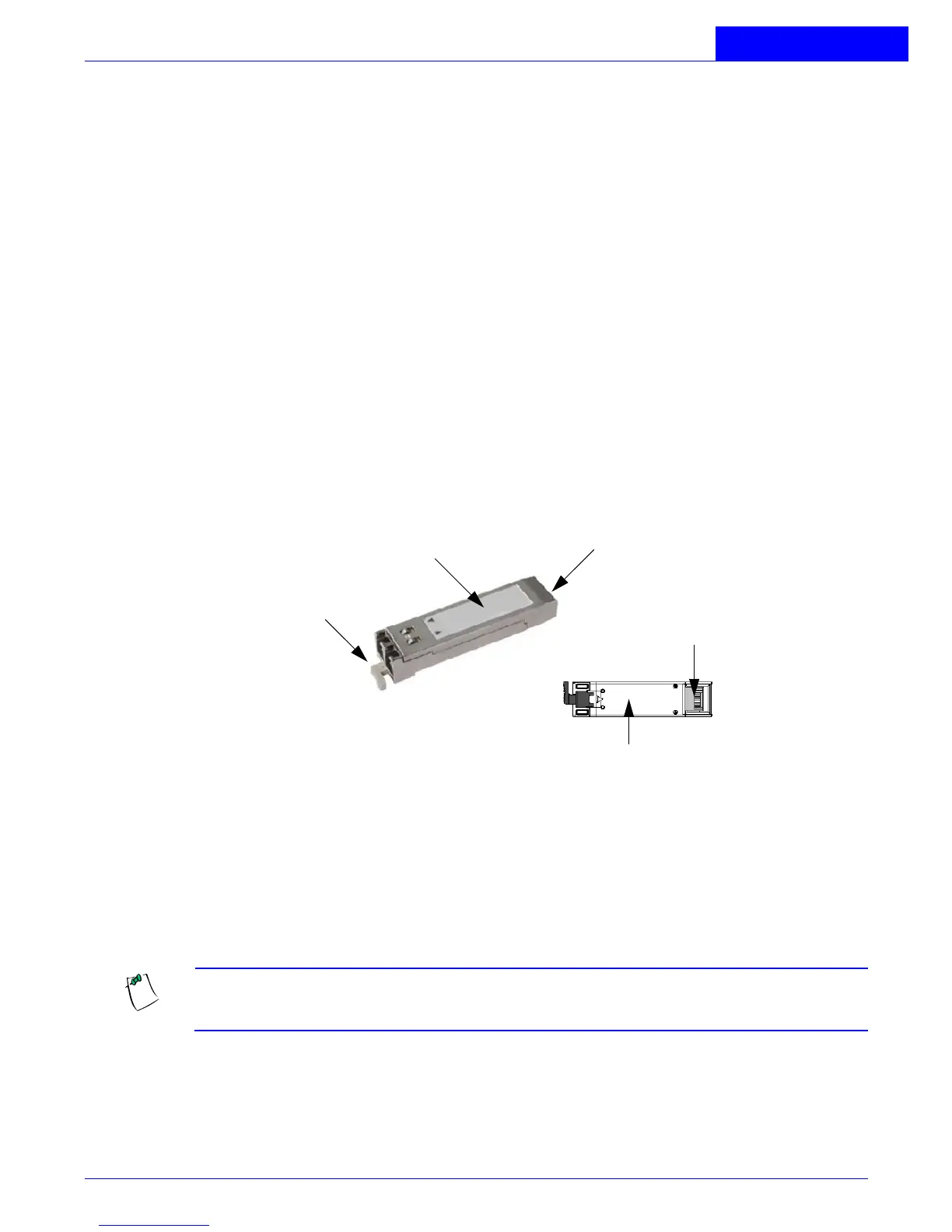
available slot. Optic modules can be hot swapped. The following figure shows a typical pluggable
optic module and its parts.
Figure 2-6:
Pluggable Optic Module
To install a pluggable optic into a port:
1.
Hold the optic module by the sides and position it so that the cutaway portion of
the module is facing down and the 20-pin connector card (rear of the optic) is
facing the empty optic slot.
NOTE:
If installed upside down, the optic will only insert halfway into the slot.
Remove the optic, turn it over, and reinstall. Do not insert the optic forcibly.
2.
Gently insert the pluggable optic module into the available slot until it seats
completely.
Ejector Lever
Rear of module
Top of module
20-pin connector
(Rear of module)
Bottom of module