24
LE-3xx/LE-4xx Hardware Installation & User Guide
REMOVABLE POWER SUPPLIES
•
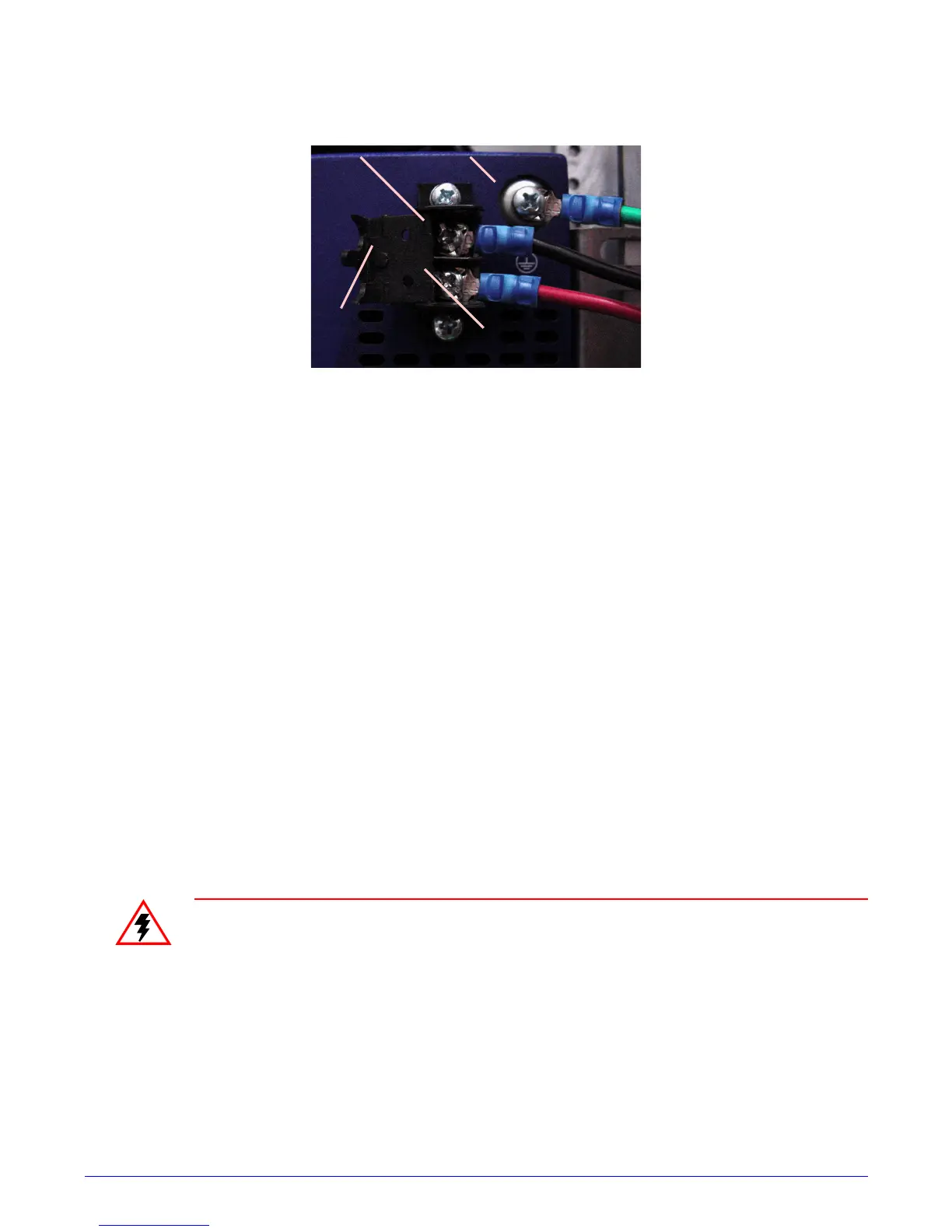
-48V return to 48 REF screw.
Figure 2-3:
DC Connector Locations
5.
After ensuring that all wire connections are secure, close the terminal block cover.
6.
Restore power to the input DC circuit.
7.
Verify that the PWR LED on the front of the device is green.
Removable Power Supplies
This section provides instructions for installing the power supplies into an LE-310, LE-311, LE-
311v, LE-327, and LE-427 devices. In general, the DC power supply has the same characteristics
as the AC version. When two power supplies are installed, the power supplies provide system
power simultaneously (load sharing). In systems with dual power supplies, additional
redundancy can be achieved by connecting each power supply to a separate input circuit. In the
event of a power failure on the first source, the second source may still be available.
Power supplies are hot-swappable, allowing one power supply to be removed and replaced while
the remaining supply will compensate to maintain uninterrupted system operation. When only
one power supply is to be installed, it should be used in the slot labelled PS1.
WARNING:
Keep hands and fingers out of the power supply bays as voltage is
present on the switch backplane when the system is operating.
WARNUNG:
Halten Sie Hände und Finger aus dem Stromversorgungsfeld
entfernt, da während des Betriebs des Systems auf der Schalterrückseite
Spannung anliegt.
AVERTISSEMENT:
En présence de tension dans le fond de panier du
commutateur pendant le fonctionnement du système, tenez les mains et les
doigts éloignés des baies d'alimentation électrique.
Ter m inal B lock
Cover
Ground
48 REF
-48 VDC