LE-3xx/LE-4xx Hardware Installation & User Guide
23
INSTALLING THE SCS/SDS DEVICE
2
3.
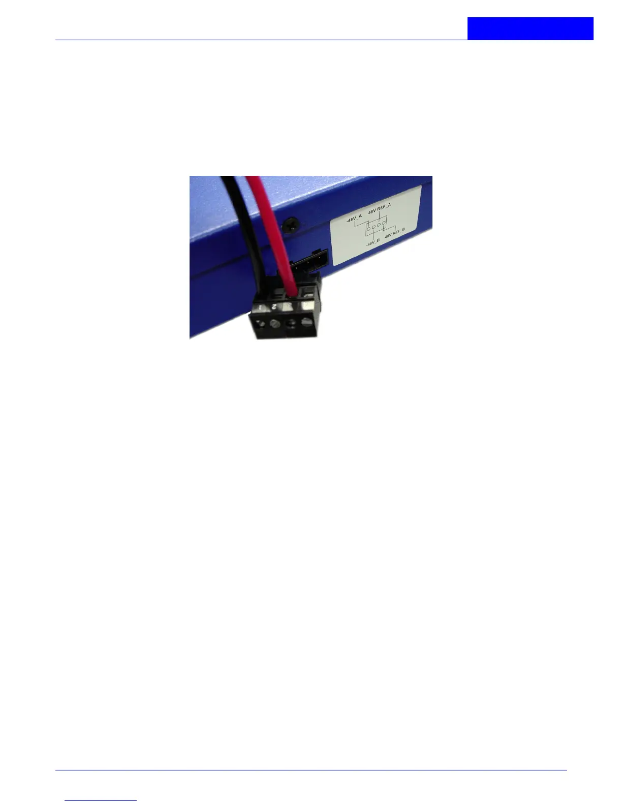
Wire the DC-input power supply to the J-9 terminal connector (supplied) according
to the label on the outside of the chassis (see
Figure 2-2
), ensuring that all
connections are secure:
•
Connect the -48V input wire to the -48V_A pin.
•
Connect the -48V return wire to the 48V REF_A pin.
Figure 2-2:
DC Wiring Diagram, J-9 Connector
4.
Plug the J-9 slotted connector into the rear of the device, making sure that it is
completely seated.
5.
Restore power to the input DC circuit.
6.
Verify that the PWR LED on the front of the device is green.
Connecting DC power to the DC power supplies:
1.
Verify that power is OFF at the DC input circuit.
2.
If present, flip the terminal block cover open.
3.
Attach appropriate lugs to the DC input wires (standard eyelet connectors are
suggested).
4.
Attach the DC input wires to the terminal block from the right of the device, as
follows (see Figure 4):
•
Ground wire to ground screw.
•
-48V wire to -48 Vdc screw.