TRANSTIG 170Pi
Manual 0-5242 6-19
TROUBLESHOOTING
6.14 Main Circuit Description
!
WARNING
Turn off power and disconnect mains supply plug from receptacle before working on the unit. Allow
two minutes for capacitors to discharge after disconnection from mains supply voltage.
Art # A-11823
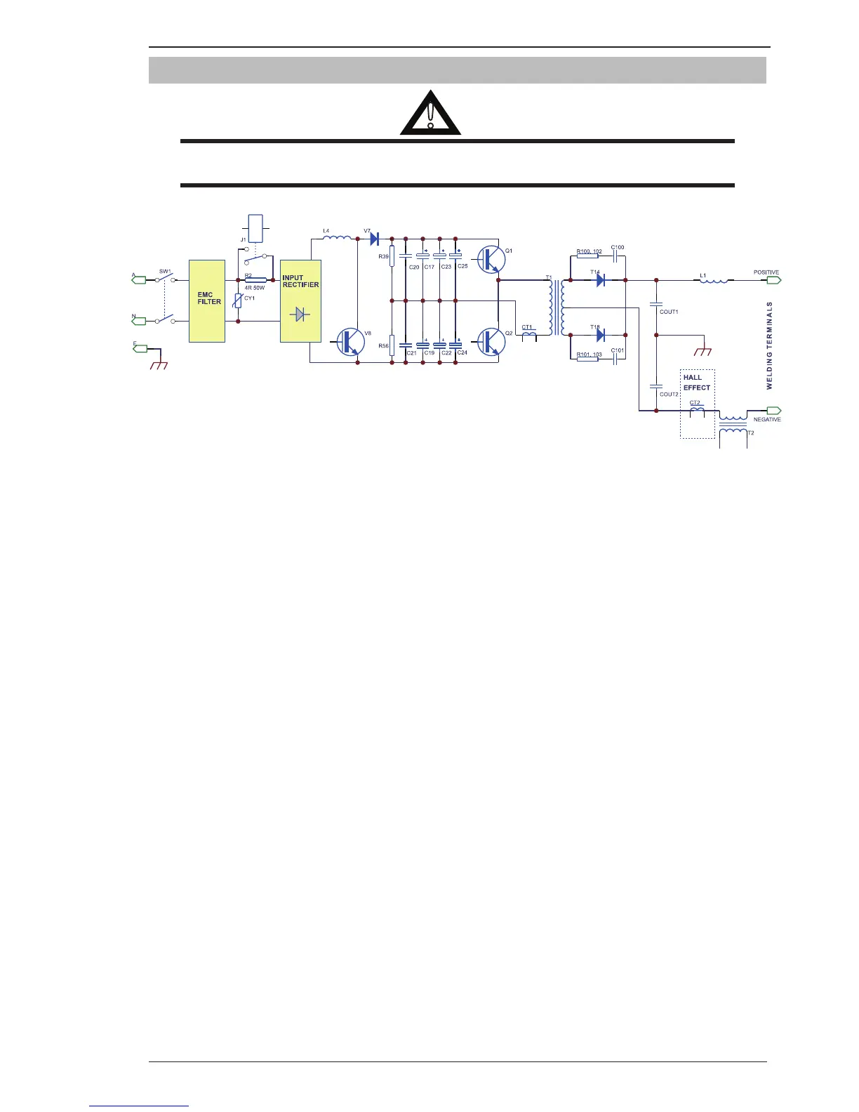
Figure 6-13: Main Circuit
The mains supply voltage is connected via a double pole switch to the input rectifiers on the main Inverter PCB
through an inbuilt EMC filter on the inverter power board. Overvoltage protection is provided by varistor CY1.
The rectifier output charges the main capacitor bank (C17, C19, C22, C23, C24 and C25) to high voltage through
PFC IGBT’s V8 and PFC diodes V7. Inrush current limiting is provided by an off board resistor R2 which is
then bypassed by relay J1 after a few seconds.
The primary igbt transistors (Q1, and Q2) switch the transformer primary at high frequency and varying duty
cycle. The transformer return wire is taken from the terminal centre of the main DC bus capacitor bank (the
voltage at this point is approximately half the DC bus voltage).
Secondary output voltage from the transformer is rectified by the output diodes (T14, to T18) to DC. This DC
is controlled by the PWM of the primary side igbt transistors, and is filtered by an inductor before connecting
to the welding output terminals.
A thermal overload device (thermal switch) is fixed to the rectifier heatsinks. When an over temperature occurs,
the control circuit inhibits the trigger, gas solenoid, and the welding output. The thermal overload indicator
LED on the front panel is illuminated.
The current transformer CT1 provides a signal to the control circuit to indicate both transformer primary cur-
rent, and also detect transformer saturation. The Hall effect current sensor CT2 is powered from regulated
+ & - 15VDC supplies and provides a voltage signal proportional to the output welding current to allow the
control circuit to regulate welding current.
High frequency is injected in HF TIG mode to the welding output through transformer T2.