TRANSTIG 170Pi
Manual 0-5242 6-9
TROUBLESHOOTING
6.10 DC Bus Voltage Measurement
Apply voltage to the Power Source.
WARNING
There are extremely dangerous voltage and power levels present inside these Power Sources. Do
not attempt to diagnose or repair unless you have had training in power electronics measurement
and troubleshooting techniques.
Once power is applied to the Power Source, there are extremely hazardous voltage and power levels present.
Do not touch any live parts.
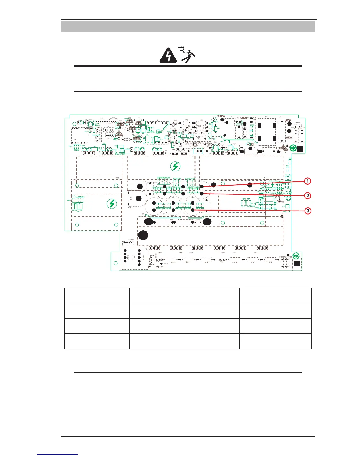
Art # A-11816
Figure 6-6: DC Bus Voltage Measurement
DC Bus Testing Multimeter Lead Placement
Voltage with Supply Voltage
ON
Upper capacitor bank
Positive meter lead to TP 1
Negative meter lead to TP 2
150-200 VDC
Lower capacitor bank
Positive meter lead to TP 2
Negative meter lead to TP 3
150-200 VDC
Overall capacitor bank
Positive meter lead to TP 1
Negative meter lead to TP 3
300-400 VDC
Table 6-9: DC BUS, Multimeter set to measure DC volts
NOTE
These DC voltages are at nominal mains supply voltage of 240VAC.