TRANSTIG 170Pi
ASSEMBLY PROCEDURE 8-4 Manual 0-5242
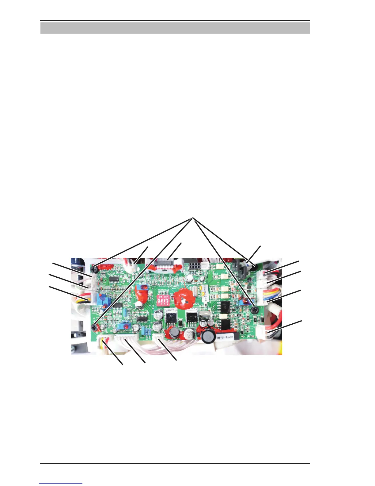
8.04 Installing Control PCB
1. Install the four screws and secure Control PCB.
2. Plug OT1 harness into OT1 connector.
3. Plug OT2 harness into OT2 connector.
4. Plug PFC harness into PFC connector.
5. Plug MB harness into MB connector.
6. Plug QF harness into QF connector.
7. Plug FAN harness into FAN connector.
8. Plug DY harness into DY connector.
9. Plug GUN harness into GUN connector.
10. Plug WV harness into WV connector.
11. Plug SOURCE harness into SOURCE connector.
12. Plug DRIVE harness into DRIVE connector.
13. Plug IFB harness into IFB connector.
14. Plug HF harness into HF connector.
15. Verify harness connections with system schematic to ensure that all connections are correct.