TRANSTIG 170Pi
DISASSEMBLY PROCEDURE 7-4 Manual 0-5242
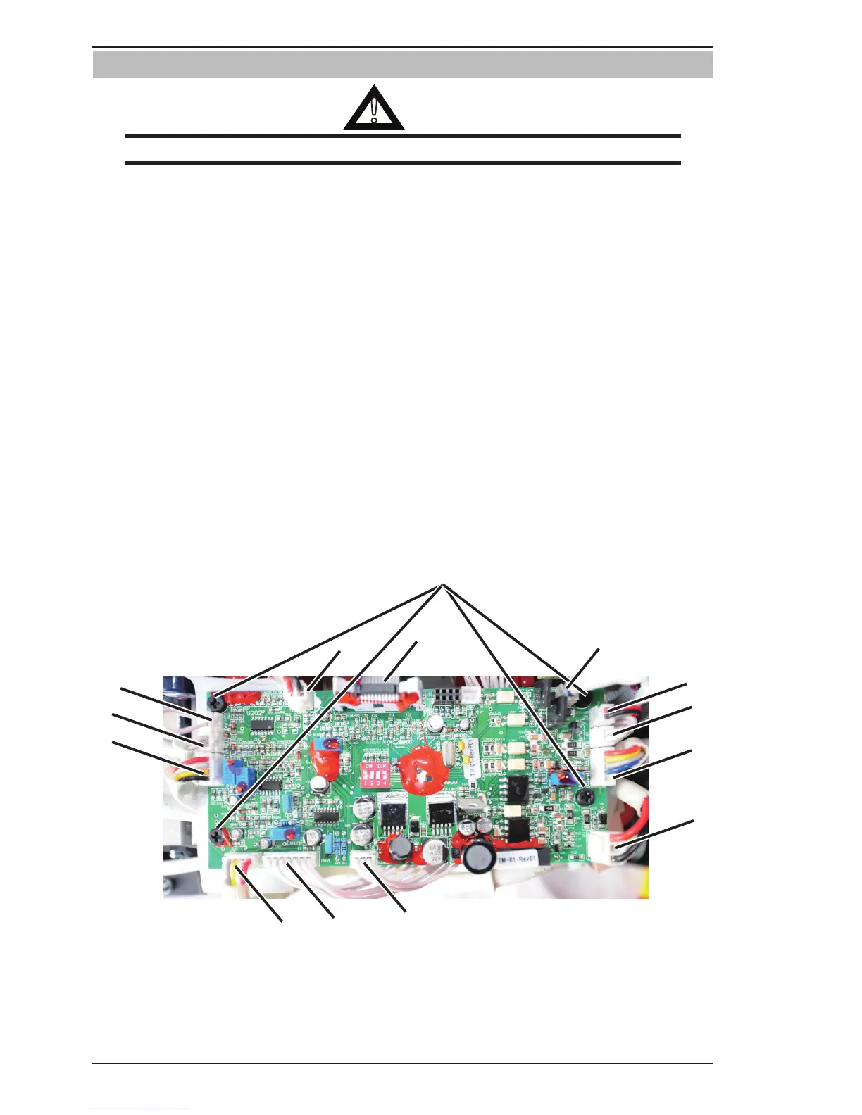
7.05 Control PCB Removal
!
WARNING
Read and follow safety information in Section 6.04 before proceeding.
1. Remove the four screws securing Control PCB.
2. Disconnect OT1 harness from OT1 connector.
3. Disconnect OT2 harness from OT2 connector.
4. Disconnect PFC harness from PFC connector.
5. Disconnect MB harness from MB connector.
6. Disconnect QF harness from QF connector.
7. Disconnect FAN harness from FAN connector.
8. Disconnect DY harness from DY connector.
9. Disconnect GUN harness from GUN connector.
10. Disconnect WV harness from WV connector.
11. Disconnect SOURCE harness from SOURCE connector.
12. Disconnect DRIVE harness from DRIVE connector.
13. Disconnect IFB harness from IFB connector.
14. Disconnect HF harness from HF connector.
Ensure to unplug all harness from control PCB.