TRANSMIG 225, 255 MIG Power Source, 255 2R MIG Wirefeeder
Sep 16, 2008 15
SECTION 7: Specifications
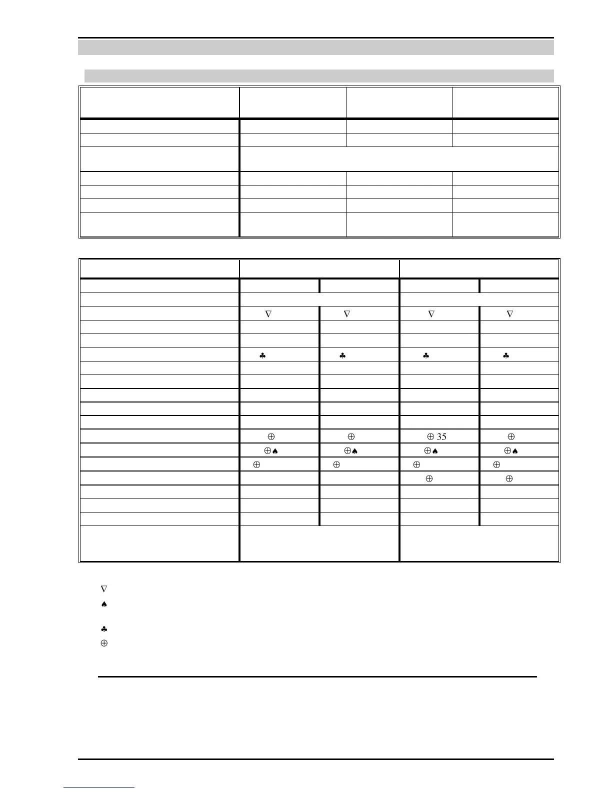
7.01 TRANSMIG 225, 255 MIG Power Source Specifications
Description (Refer NOTE 2)
Plant Dimensions (including cylinder carrier
& excluding wheels)
H 1000mm x W 430mm x D 880mm
Maximum Inlet Gas Pressure
Argon based mixed gases &
C02
Argon based mixed gases &
C02
Argon based mixed gases &
C02
Description (Refer NOTE 2)
TRANSMIG 225 MIG Power Source
TRANSMIG 255 MIG Power Source
Number of Phases & Frequency
Rated Input Current @ 100% Duty Cycle
Rated kVA @ 100% Duty Cycle
Power Factor @ max. output
Open Circuit Voltage Range
Rated Outlet Maximum Duty Cycle
100% Duty Cycle Output Rating
Operating Temperature Range
Number of Output Voltage Switch Settings
Hard Wire: 0.6mm – 0.9mm
Soft Wire: 0.8mm - 1.2mm
Fluxcored Wire: 0.6mm – 1.2mm
Hard Wire: 0.6mm – 0.9mm
Soft Wire: 0.8mm – 1.2mm
Fluxcored Wire: 0.6mm – 1.2mm
Table 2 – Power Source Specifications
The Rated Input Current should be used for the determination of cable size & supply requirements.
Motor start fuses or thermal circuit breakers are recommended for this application. Check local requirements for your situation in
this regard.
Generator Requirements at the Maximum Output Duty Cycle.
Reduced output ratings apply with the supplied 15A supply cable. To achieve these ratings the 15A supply cable and plug must be
replaced with a larger plug and cable as specified in section 8.04. This must be carried out be a qualified electrical tradesperson.
NOTE 2
Due to variations that can occur in manufactured products, claimed performance, voltages, ratings, all capacities,
measurements, dimensions and weights quoted are approximate only. Achievable capacities and ratings in use and operation
will depend upon correct installation, use, applications, maintenance and service.