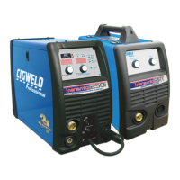
TRANSMIG 225, 255 MIG Power Source, 255 2R MIG Wirefeeder
Sep 16, 2008 21
10.05 Torch Polarity Lead (Compact models only)
This lead selects the welding voltage polarity of the electrode wire. Plug it into the positive welding terminal (+) when using steel,
stainless steel or aluminium electrode wire. Plug the Torch Polarity Lead into the negative welding terminal (-) when using gasless
electrode wire. If in doubt, consult the manufacturer of the electrode wire for the correct polarity.
10.06 Positive Welding Terminal
Positive Welding Terminal. Welding current flows from the Power Source via heavy duty bayonet type terminals. It is essential, however,
that the male plug is inserted and turned securely to achieve a sound electrical connection.
10.07 Negative Welding Terminal
Negative Welding Terminal. Welding current flows from the Power Source via heavy duty bayonet type terminals. It is essential,
however, that the male plug is inserted and turned securely to achieve a sound electrical connection.
CAUTION 3
Loose welding terminal connections can cause overheating and result in the male plug being fused in the terminal.
10.08 Torch Connector (Compact models only)
The MIG torch connects to this outlet.
10.09 Thermal Overload
The critical component for thermal protection is the rectifier stack, which is fitted with a thermal overload cut out device. If the overload
operates then the machine should be left to cool for approximately 15 minutes before resuming welding. The thermal overload will not
operate and there will be no danger of transformer damage if the Power Source is operated within its duty cycle.
The TRANSMIG 225, 255 Compact Power Source has a front panel indication of Thermal Overload.
The TRANSMIG 255 Remote Power Source has a front panel indication of Thermal Overload on the 255 2R Wirefeeder.
10.10 Spot Selector Switch
The SPOT SELECTOR switch selects Spot welding mode.
This mode of welding is used to weld two plates together at a desired location by melting the top & bottom plates together to form a
nugget between them. The spot time period is set by the SPOT TIME control knob.
10.11 Spot Timer
With the SPOT SELECTOR switch in the SPOT position, the SPOT TIME knob controls the duration of a single spot weld.
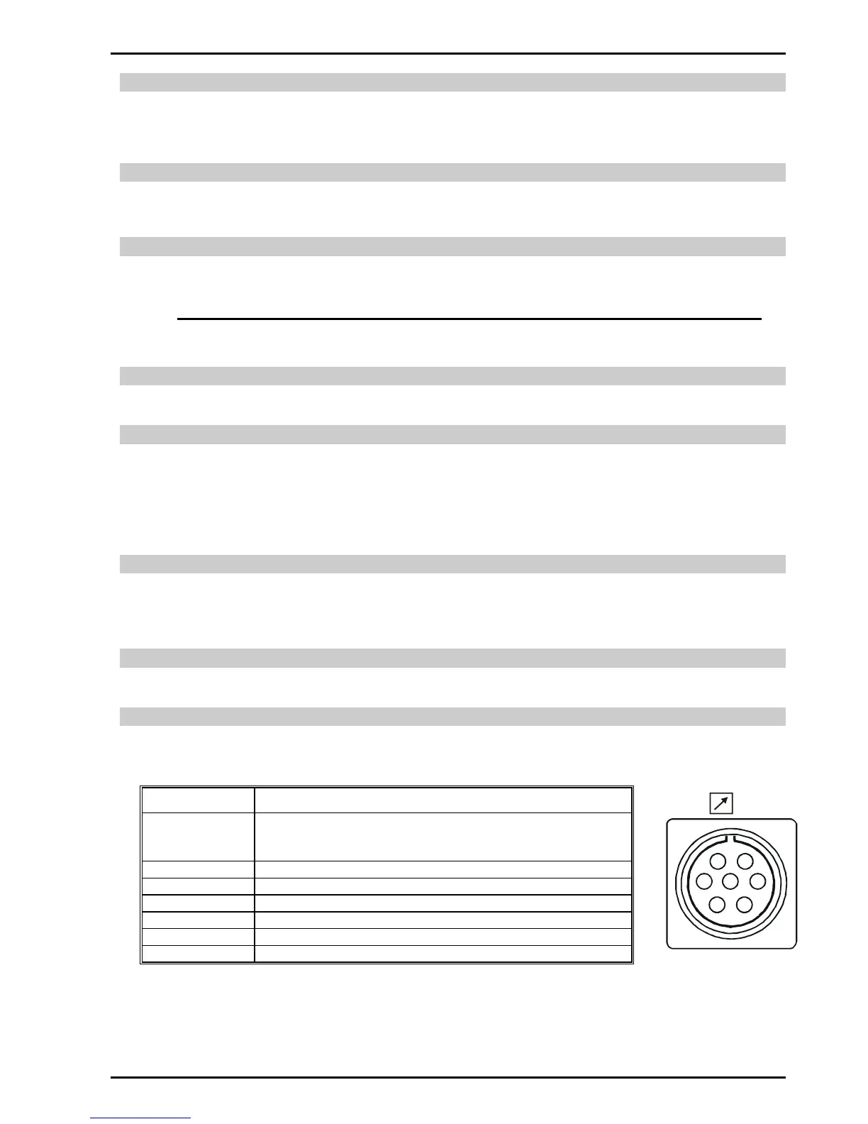
10.12 Wirefeeder Control Socket (Remote model only)
The WIREFEEDER 7 pin receptacle is used to connect a Wirefeeder to the welding Power Source circuitry:
To make connections, align keyway, insert plug, and rotate threaded collar fully clockwise. The socket information is included in the event
the supplied cable is not suitable and it is necessary to wire a plug or cable to interface with the WIREFEEDER 7-pin receptacle.