TRANSMIG 225, 255 MIG Power Source, 255 2R MIG Wirefeeder
20 Sep 16, 2008
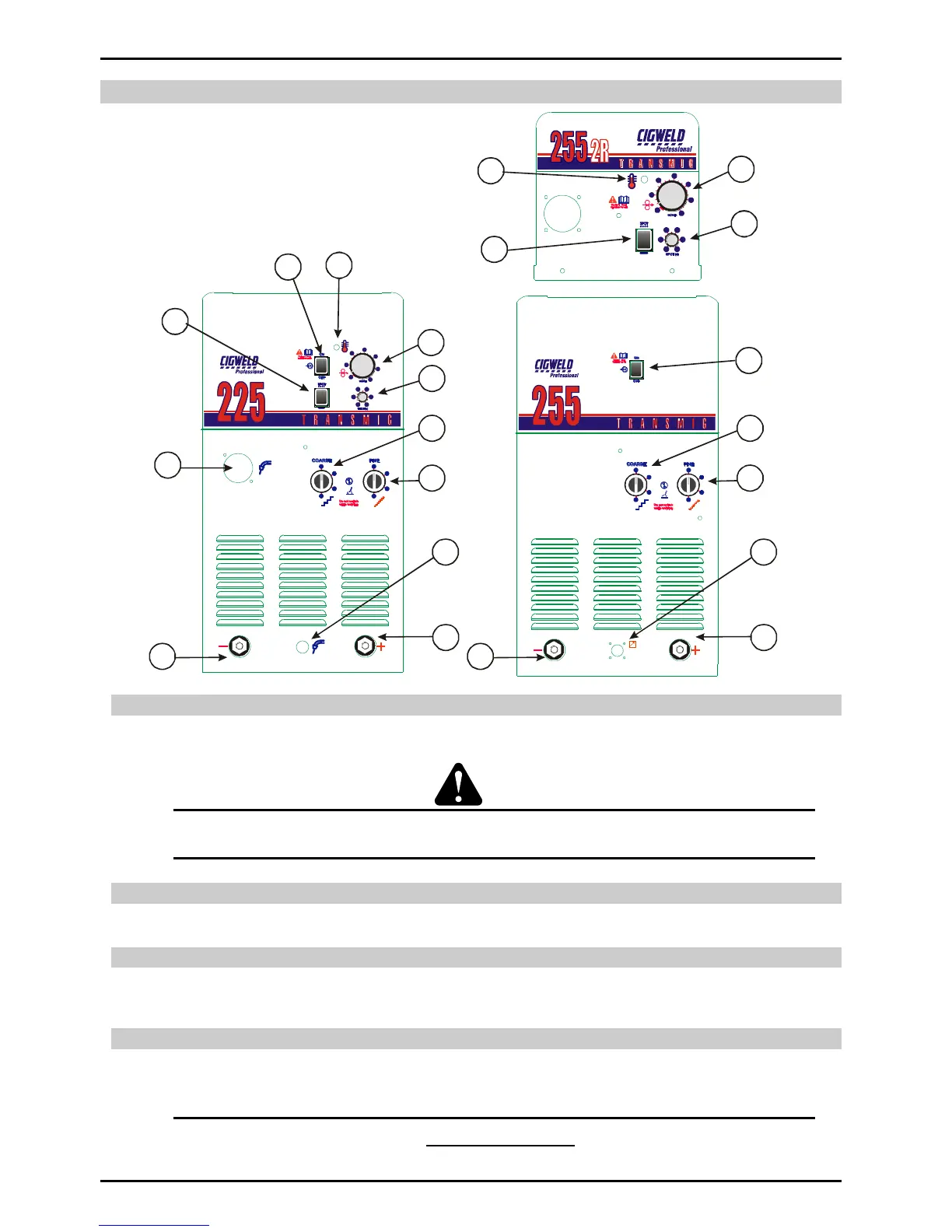
SECTION 10: Power Source and Wirefeeder Controls, Indicators and Features
10.01 Standby switch with in-built Indicator Light
The indicator light is provided to indicate when the TRANSMIG 225, 255 MIG Power Source is connected to the Mains Supply voltage.
With the switch in the STANDBY position, the auxiliary power and the fan are turned off.
WARNING 9
When the light is lit, the machine is connected to the Mains supply voltage and the internal electrical components are at
Mains voltage potential.
10.02 Wirespeed Control
The Wirespeed Control knob controls the welding current via the electrode wirefeed rate. ie the speed of the wirefeed motor.
10.03 Output Voltage Control Switch (Coarse)
The Coarse Voltage Control switch increases the voltage (in larger increments than the Fine switch) as it is rotated in the clockwise
direction.
10.04 Output Voltage Control Switch (Fine)
The Fine Voltage Control switch increases the voltage (in smaller increments than the Coarse switch) as it is rotated in the clockwise
direction.
CAUTION 2
The Coarse and Fine Voltage Control switches MUST NOT BE SWITCHED during the welding process