TRANSMIG 225, 255 MIG Power Source, 255 2R MIG Wirefeeder
24 Sep 16, 2008
SECTION 12: Basic Welding Technique
12.01 Setting of the Power Source & Wirefeeder
Power source and Wirefeeder setting requires some practice by the operator, as the welding plant has two control settings that
have to balance. These are the Wirespeed control and the welding Voltage Control. The welding current is determined by the
Wirespeed control, the current will increase with increased Wirespeed, resulting in a shorter arc. Less wire speed will reduce the
current and lengthen the arc. Increasing the welding voltage hardly alters the current level, but lengthens the arc. By decreasing
the voltage, a shorter arc is obtained with a little change in current level.
When changing to a different electrode wire diameter, different control settings are required. A thinner electrode wire needs
more Wirespeed to achieve the same current level.
A satisfactory weld cannot be obtained if the Wirespeed and Voltage settings are not adjusted to suit the electrode wire diameter
and the dimensions of the work piece.
If the Wirespeed is too high for the welding voltage, “stubbing” will occur as the wire dips into the molten pool and does not melt.
Welding in these conditions normally produces a poor weld due to lack of fusion. If, however, the welding voltage is too high,
large drops will form on the end of the wire, causing spatter. The correct setting of voltage and Wirespeed can be seen in the
shape of the weld deposit and heard by a smooth regular arc sound.
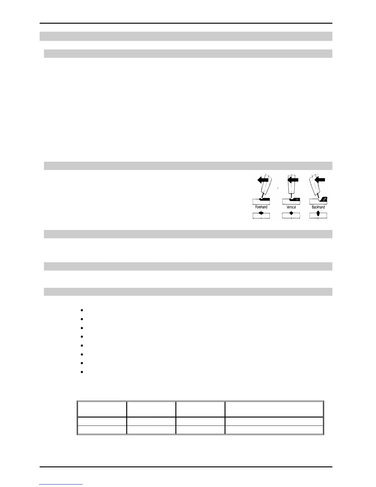
12.02 Position of MIG Torch
The angle of MIG torch to the weld has an effect on the width of the weld.
12.03 Distance from the MIG Torch Nozzle to the Work Piece
The electrode wire stick out from the MIG Torch nozzle should be between 10mm to 20.0mm. This distance may vary
depending on the type of joint that is being welded.
12.04 Travel Speed
The speed at which the molten pool travels influences the width of the weld and penetration of the welding run.
12.05 Electrode Wire Size Selection
The choice of Electrode wire size and shielding gas used depends on the following
Thickness of the metal to be welded
Type of joint
Capacity of the wire feed unit and Power Source
The amount of penetration required
The deposition rate required
The bead profile desired
The position of welding
Cost of the wire
Weld metal deposition rate is proportional to current density. Current density is defined as the current per cross sectional area of
the electrode wire and is normally expressed as amps per mm
2
. An example is shown below