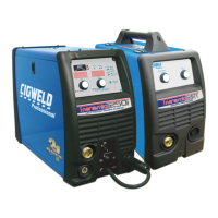
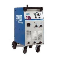
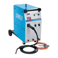
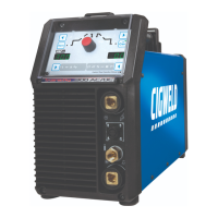
TRANSMIG 225, 255 MIG Power Source, 255 2R MIG Wirefeeder
18 Sep 16, 2008
SECTION 9: Set up for the TRANSMIG 225, 255 MIG Power Source
9.01 Power Source Connections
a) Remove all packaging materials.
b) Connect the work lead to the negative welding terminal (-) [positive welding terminal (+) for flux cored electrode wire]. If in
doubt, consult the electrode wire manufacturer.
c) Position a gas cylinder on the rear tray of the Power Source and lock securely to the Power Source cylinder bracket with
the chain provided. If this arrangement is not used or the Power Source is not fitted with a gas cylinder tray then ensure
that the gas cylinder is secured to a building pillar, wall bracket or otherwise securely fixed in an upright position.
9.02 Wirefeeder Connections (Remote models only)
a) Connect the welding power cable from the Wirefeeder's interconnection cables to the positive welding terminal (+)
[negative welding terminal (-) for flux cored electrode wire]. If in doubt, consult the electrode wire manufacturer.
b) Connect the control cable from the Wirefeeder to the socket on the Power Source.
c) Fit the gas regulator and flowmeter to the gas cylinder then connect the gas hose from the rear of the Wirefeeder to the
Flowmeter outlet.
d) Dual groove feed rollers are supplied as standard. They can
accommodate 0.9 / 1.2 diameter hard wires. Select the roller required with
the chosen wire size marking facing outwards.
e) Fit the electrode wire spool to the wire reel hub. Ensure that the drive
dog-pin engages the mating hole in the wire spool. Push the 'R' clip into place to retain the wire spool securely. The
electrode wire should feed from the bottom of the spool.
f) MIG Torch, EURO MIG Torch Connection
Fit the MIG Torch to the Wirefeeder by pushing the torch connector into the brass torch adaptor and screwing the plastic
torch nut clockwise to secure the torch to the torch adaptor. Remove the contact tip from the torch handset.
9.03 Wirefeeder Connections (Compact models only)
a) Connect the TORCH power cable to the positive welding terminal (+) [negative welding terminal (-) for flux cored electrode
wire]. If in doubt, consult the electrode wire manufacturer.
b) Fit the gas regulator and flowmeter to the gas cylinder then connect the gas hose from the rear of the Power Source to the
Flowmeter outlet.
c) Dual groove feed rollers are supplied as standard. They can
accommodate 0.6 / 0.8 diameter hard wires. Select the roller required with
the chosen wire size marking facing outwards.
d) Fit the electrode wire spool to the wire reel hub. Ensure that the drive
dog-pin engages the mating hole in the wire spool. Push the 'R' clip into place to retain the wire spool securely. The
electrode wire should feed from the bottom of the spool.
e) MIG Torch, EURO MIG Torch Connection
Fit the MIG Torch to the Power Source by pushing the torch connector into the brass torch adaptor and screwing the plastic
torch nut clockwise to secure the torch to the torch adaptor. Remove the contact tip from the torch handset.
9.04 Common Connections
a) Lift up the wire feeder pressure levers and pass the electrode wire through the inlet guide, between the rollers, through the
centre guide, between the rollers, through the outlet guide and into the MIG torch.