TRANSMIG 225, 255 MIG Power Source, 255 2R MIG Wirefeeder
Sep 16, 2008 19
b) Lift up the wire feeder pressure levers and pass the electrode wire through the inlet guide, between the rollers, through the
centre guide, between the rollers, through the outlet guide and into the MIG torch.
WARNING 7
DO NOT WEAR GLOVES WHILE THREADING THE WIRE OR CHANGING THE WIRE SPOOL.
c) Lower the pressure levers and with the torch lead reasonably straight, feed the electrode wire through the torch. Fit the
appropriate contact tip, eg a 0.8mm tip for 0.8mm wire.
d) Press the Torch switch to feed the wire through the torch.
WARNING 8
The electrode wire will be at welding voltage potential whilst it is being fed through the wirefeeder system if the wire is
fed by using the TORCH SWITCH
9.05 Drive Roller Pressure Adjustment
The moveable rollers apply pressure to the grooved feed rollers via a scaled adjustable tension screw. These devices should be
adjusted to a minimum pressure that will provide satisfactory WIREFEED without slippage. If slipping occurs, and inspection of
the wire contact tip reveals no wear, distortion or burn back jam, the conduit liner should be checked for kinks and clogging by
metal flakes and swarf. If it is not the cause of slipping, the feedroll pressures can be increased by rotating the scaled tension
screws clockwise. The use of excessive pressure may cause rapid wear of the feed rollers, shafts and bearing.
9.06 Wire Reel Brake
The wire reel hub incorporates a friction brake which is adjusted during manufacture for optimum breaking. If it is considered
necessary, adjustment can be made by turning the large nut inside the open end of the hub clockwise to tighten the brake.
Correct adjustment will result in the wire reel circumference continuing no further than 20mm after release of the trigger. The
electrode wire should be slack without becoming dislodged from wire spool
CAUTION 1
Overtension of brake will cause rapid wear of mechanical WIREFEED parts, overheating of electrical componentry and
possibly an increased incidence of electrode wire Burnback into contact tip
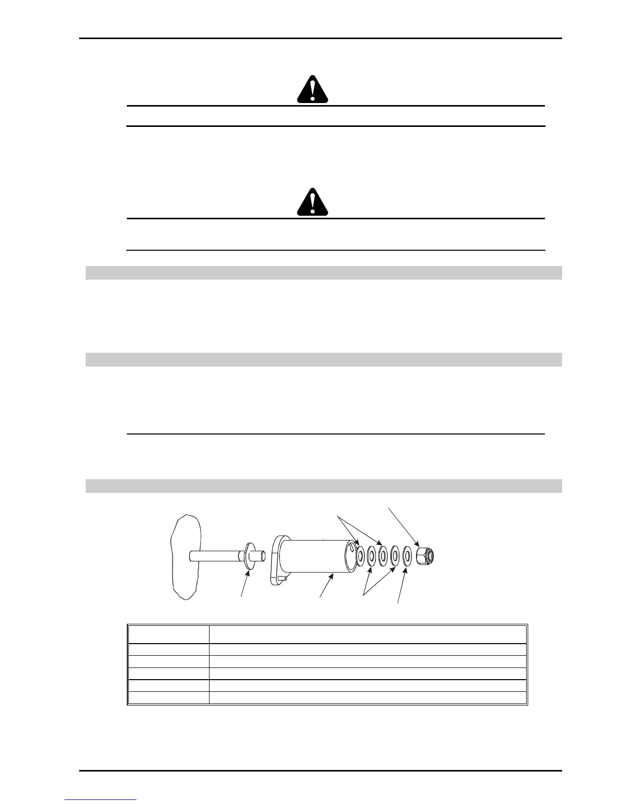
9.07 Wire Reel Hub Assembly