Do you have a question about the CIGWELD 255 and is the answer not in the manual?
Explains manual structure, notation (WARNING, CAUTION, NOTE), and how to use the document effectively.
Details how to find and record the unit's identification numbers (specification, model, serial).
Instructions for checking equipment upon receipt, reporting damage, and ordering manuals.
Outlines user's responsibility for installation and managing electromagnetic disturbances.
Guides users on assessing the surrounding environment for potential electromagnetic interference.
Details methods like mains supply connection, cable management, and bonding to minimize emissions.
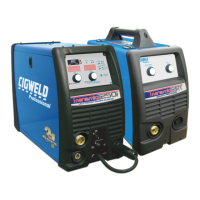
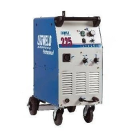
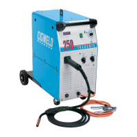
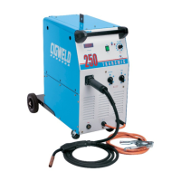
Introduces the TRANSMIG 225/255 MIG welder, its features, and compliance with standards.
Clarifies user obligations regarding equipment use, maintenance, and modifications.
Explains the meaning of duty cycle and its graphical representation for the welding unit.
Lists essential safety precautions for operators during welding operations.
Details necessary personal protective equipment (PPE) like gloves, clothing, and face shields.
Provides step-by-step instructions for performing resuscitation on electric shock victims.
Lists detailed technical specifications for TRANSMIG 225 and 255 power sources (mass, dimensions, voltage, current).
Lists available optional accessories for the welding equipment, including part numbers and descriptions.
Advises on suitable environments for welding equipment, avoiding hazards like electric shock.
Provides guidelines for selecting an appropriate location for the welder, considering factors like moisture and airflow.
Emphasizes the importance of adequate ventilation in the welding area to prevent fume hazards.
Details mains supply voltage, lead sizes, fuse recommendations, and duty cycle ratings.
Explains how to rewire the unit for 220VAC operation and provides supply lead connection diagrams.
Guides on connecting the power source, work lead, and gas cylinder securely.
Details connecting the wirefeeder, control cable, gas hose, and torch for remote models.
Outlines connecting the torch, gas hose, wire spool, and wire feeder for compact models.
Explains threading the electrode wire through the wire feeder and torch assembly.
Instructs on adjusting drive roller pressure for optimal wire feeding and preventing slippage.
Explains how to adjust the wire reel brake for proper wire spool tension and preventing issues.
Details the components and assembly of the wire reel hub, including a parts list.
Describes the standby switch and indicator light function for power connection status.
Explains the function of the Wirespeed Control knob for adjusting welding current.
Details the function of the Coarse Voltage Control switch for adjusting welding voltage.
Explains the function of the Fine Voltage Control switch for fine-tuning welding voltage.
Explains how to use the Torch Polarity Lead for selecting electrode wire polarity.
Identifies the positive welding terminal and stresses secure connection for current flow.
Identifies the negative welding terminal and stresses secure connection for current flow.
Indicates the outlet for connecting the MIG torch to compact models.
Explains the thermal overload protection mechanism and cooling procedure.
Describes the SPOT SELECTOR switch for engaging spot welding mode.
Details the SPOT TIME control for setting the duration of a single spot weld.
Describes the 7-pin receptacle for connecting a wirefeeder and its socket pin functions.
Explains burnback time, its factory setting, and adjustment for optimum wire feed.
Lists all components of the 250A TWECO MIG Torch with part numbers and quantities.
Provides a table of contact tips for standard/tapered and heavy duty MIG torches by wire size.
Lists part numbers for MIG torch conduits based on wire size and type (hard/soft).
Step-by-step guide for installing a new wire conduit into the MIG torch cable assembly.
Provides instructions for routine maintenance of the MIG torch conduit.
Explains how to balance Wirespeed and Voltage controls for optimal welding results.
Discusses the effect of MIG torch angle on weld width and shows diagrams.
Specifies the recommended distance between the torch nozzle and the workpiece for welding.
Explains how travel speed affects weld width and penetration.
Lists factors influencing electrode wire size and shielding gas selection, plus deposition rates.
Provides instructions for regularly cleaning the drive rolls to ensure proper wire feeding.
Introduces general troubleshooting approaches for GMAW problems like porosity and inconsistent wire feed.
Lists faults and causes related to gas issues leading to weld porosity.
Details faults and causes for inconsistent wire feed, such as spool brake, roller size, and liner issues.
Provides a fault-cause-remedy guide for common welding issues like undercut, lack of penetration, and spatter.
Lists common power source and wirefeeder faults and their remedies, like indicator lights and wire feed issues.
| Model | CIGWELD 255 |
|---|---|
| Efficiency | 85% |
| Power Factor | 0.93 |
| Welding Processes | MIG (GMAW) |
| Phase | 3-Phase |