DIN
GND
PS3
GND
PS2
GND
PS1
PWR
A B PWR GND
MODULE PORT
IN+
IN-
GND
R-
Y+
THERMO-
DIGITAL
INPUTS
TRANS-
DUCER
PORT
TC2
Permissive +
-
Proof of Closure +
-
PS2
PS1
Transducer
Port
Transducer
Hot Surface
Thermocouple 1
R-
Y+
Hot Surface
Thermocouple 2
R-
Y+
+
-
+
PWR
+
-
GND
8
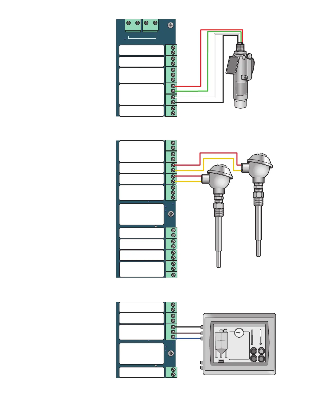
1.2.6 Transducer Port Input
The Transducer Port input accepts
mulple dierent transducer types.
The Transducer Port input can be
used as a source for the Processes
and Shutdowns (Image 1.2.6).
1.2.7 Thermocouple
Inputs 1 & 2
Thermocouple inputs 1 & 2 accept
k-type thermocouples. They can be
used as sources for the Processes and
Shutdowns. If they are not used they
need to be jumpered (Image 1.2.7).
1.2.8 Modbus RS-485
To use Modbus communicaon,
use the RS-485 PORT on the board,
aaching the A+ and B- wiring as well
as the GND to the external PLC or
communicaon device. Nocaons
of alarms can also be retrieved via
Modbus (Image 1.2.8).
VLV B
DIN
GND
PS3
GND
PS2
GND
PS1
PWR
A B PWR GND
MODULE PORT
IN+
IN-
GND
R-
B-
A+
Y+
GND
Y+
R-
THERMO-
COUPLE
PORT
RS485
PORT
ALARM
OUTPUT
DOUT-
DOUT-
AUXIO
GND
DOUT+
GND
OPN-G
GND
CLS-R
OPN-G
GND
CLS-R
MAIN
VALVE
BATTERY-IN
GND
SOLAR
GND
PWR-OUT
BATTERY-OUT
PILOT
VALVE
POWER
PORT
DIGITAL
OUTPUTS
GND GND
GROUND
GND GND
DIGITAL
INPUTS
TRANS-
DUCER
PORT
TC2
TC1
ARControl BMS
Alarm -
+
Independent
Process Valve
+
-
Pilot Status +
-
+
-
+
Process 1 Valve
Process 2 Valve
+
-
+
Pilot Valve
Process 3 Valve
Customer External PLC
Permissive +
-
Proof of Closure +
-
PS2
PS1
Transducer
Port
Hot Surface
Thermocouple 1
R-
Y+
Thermocouple 2
Y+
GND
B-
A+
Modbus
RS-485
Image 1.2.8 · Modbus RS-485 wiring
Image 1.2.7 · Thermocouple (TC1 & TC2) input wiring
Image 1.2.6 · Transducer port input wiring
VLV B
DIN
GND
PS3
GND
PS2
GND
PS1
PWR
A B PWR GND
MODULE PORT
IN+
IN-
GND
R-
B-
A+
Y+
GND
Y+
R-
THERMO-
COUPLE
PORT
RS485
PORT
ALARM
OUTPUT
DOUT-
DOUT-
AUXIO
GND
DOUT+
GND
OPN-G
GND
MAIN
VALVE
BATTERY-IN
GND
SOLAR
GND
PWR-OUT
BATTERY-OUT
PILOT
VALVE
POWER
PORT
DIGITAL
OUTPUTS
GND GND
GROUND
GND GND
DIGITAL
INPUTS
TRANS-
DUCER
PORT
TC2
TC1
MAIN
VLV A
PILOT
Thermocouple 1 & 2
ARControl BMS
Alarm -
+
Independent
Process Valve
+
-
Pilot Status +
-
+
-
+
Process 1 Valve
Process 2 Valve
+
-
+
Pilot Valve
Process 3 Valve
+
-
+
Permissive +
-
Proof of Closure +
-
PS2
PS1
Transducer
Port
Hot Surface
Thermocouple 1
R-
Y+
Hot Surface
Thermocouple 2
R-
Y+
GND
B-
A+
Modbus
RS-485
PWR
+
-
GND