7
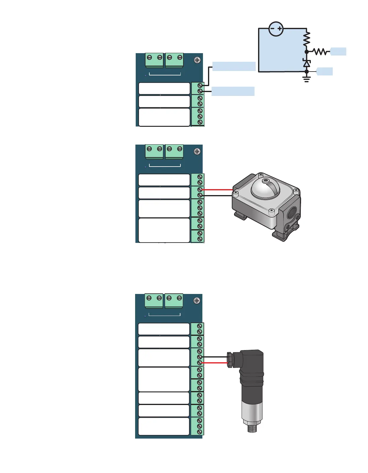
1.2.3 PERMISSIVE (DIN) Input
The PERMISSIVE input is used to
shutdown the system if it is acve.
Connect the input to a PLC or some
other external switch. By default,
the input is acve when the circuit is
open but this can be changed in the
IO sengs. It is internally pulled up to
5 VDC. If it is not used it needs to be
jumpered (Image 1.2.3).
1.2.4 Proof of Closure Input
The PROOF OF CLOSURE input is used
to check that a valve is closed before
the system aempts to ignite.
Important! Failure of this test will
transion the system to the POC
FAILURE state.
Connect the input to a valve’s status
output, pressure switch, or other
device intended to prove the state of
the valve. By default, it is acve when
the circuit is open but this can be
changed in the IO sengs. The input
is internally pulled up to 5 VDC. If this
input is not being used it needs to be
jumpered (Image 1.2.4).
1.2.5 Pressure Switches PS1
& PS2
The Pressure Switch inputs, PS1
& PS2, are generic digital inputs.
They can be used as sources for the
Shutdowns.
By default, they are acve when the
circuit is open but this can be changed
in the IO sengs. They are internally
pulled up to 5 VDC (Image 1.2.5).
DIN
GND
PS3
GND
PS2
GND
PS1
PWR
A B PWR GND
MODULE PORT
IN+
IN-
GND
DIGITAL
INPUTS
TRANS-
DUCER
PORT
Permissive +
-
Proof of Closure +
-
PS2
PS1
Transducer
Port
+
-
+
PWR
+
-
GND
IN
GND
5VDC
1MΩ
10KΩ
DIN
GND
PS3
GND
PS2
GND
PS1
A B PWR GND
MODULE PORT
DIGITAL
INPUTS
Permissive +
-
Proof of Closure +
-
PS2
PS1
Permissive IN
GND
+
-
+
DIN
GND
PS3
GND
PS2
GND
PS1
PWR
A B PWR GND
MODULE PORT
IN+
IN-
GND
R-
B-
A+
Y+
GND
Y+
R-
THERMO-
COUPLE
PORT
RS485
PORT
DIGITAL
INPUTS
TRANS-
DUCER
PORT
TC2
TC1
Permissive +
-
Proof of Closure +
-
PS2
PS1
Transducer
Port
Hot Surface
Thermocouple 1
R-
Y+
Hot Surface
Thermocouple 2
R-
Y+
GND
B-
A+
Modbus
RS-485
+
-
+
PWR
+
-
GND
Image 1.2.3 · PERMISSIVE input wiring
Image 1.2.4 · Proof of closure input wiring
Image 1.2.5 · Pressure switch input wiring
Note: If Pressure Switches
are not used they should be
jumpered