3-78
Cisco Aironet 1552 Series for Hazardous Locations Installation Guide
Chapter 3 Installing the 1552 Series Access Points in Hazardous Locations
Powering the Access Point
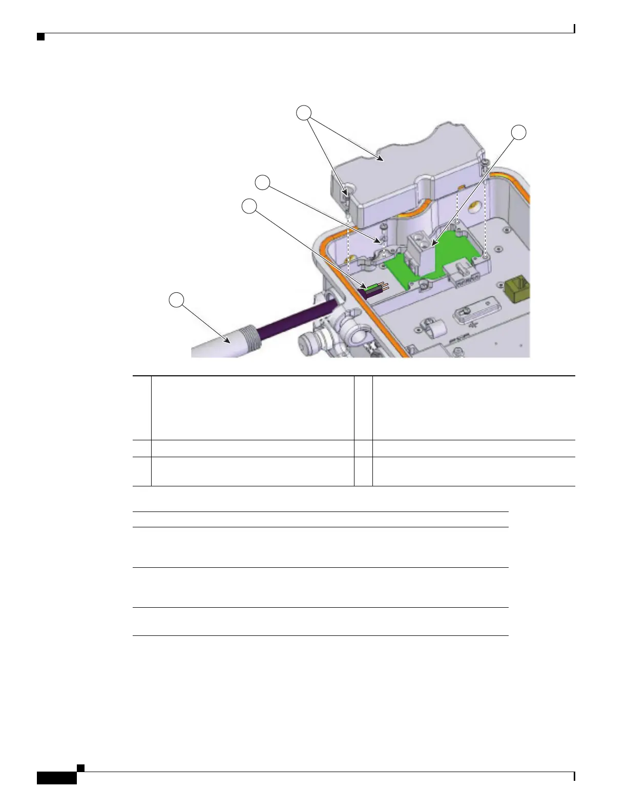
Figure 3-24 AC Power Installation—Model AIR-CAP1552H-A-K9
Step 3
Remove the cover and set it aside.
Step 4 Route the AC power cable through the 1/2-NPT port.
Step 5 Use a wire stripper tool to remove the insulation from each wire. Remove only enough wire to provide
a solid connection in the terminal block. The hot wires should have no bare wire exposed after the
connection is made.
Step 6 Insert the ground wire into the provided ground lug and use a crimping tool to secure the connection.
1 Customer-supplied 1/2” NPT Pipe (North
American/ATEX) or sheathed cable (ATEX
only).
4 AC Entry Cover
• Loosen the captive screws (3x) to open
cover.
• Reattach after harness has been installed.
2 Customer-supplied harness 5 Terminal block
3 Attach GND wire to terminal ring. Attach
terminal ring to chassis as shown.
Notes
1 The installer/integrator is responsible for supplying the appropriate
certified components as part of the overall designed system and must
maintain the access point environmental integrity of IP67 rating.
2 The water-tight gland device selected by the installer/integrator must be
equal to or greater (better) than the specifications listed for device
referenced as Sealcon CD-13AR-EX with a Buna-N O-ring.
3 The torque specification for water-tight glands are 6 to 7 ft-lbs (8.1 to 9.5
N.m).
343734
1
2
3
4
5