1-3
Software Configuration Guide For Cisco 2600 Series, Cisco 3600 Series, and Cisco 3700 Series Routers
OL-1957-04
Chapter1 Understanding Interface Numbering and Cisco IOS Software Basics
Understanding Interface Numbering
Interface (port) numbers begin at 0 for each interface type, and continue from right to left and (if
necessary) from bottom to top.
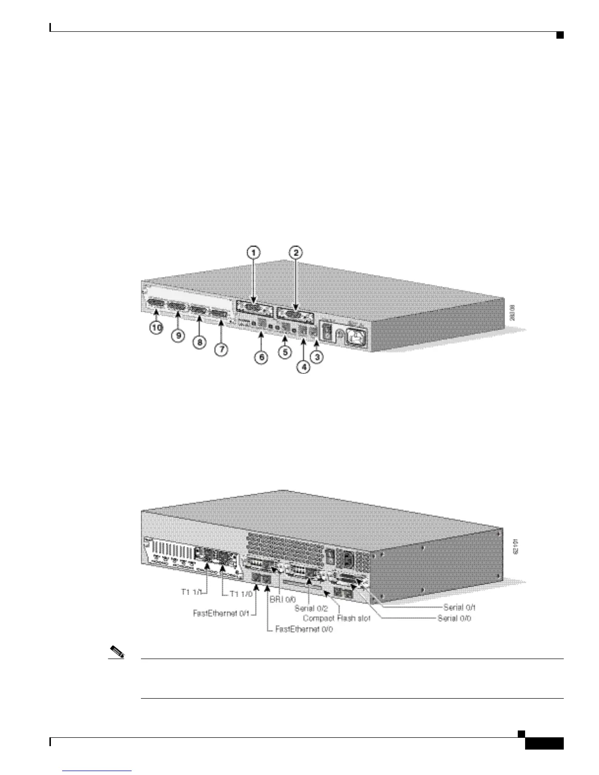
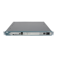
Figure1-1 below shows a router of 1 RU height with:
• A WIC in each WIC slot (containing interface Serial 0/0 in physical slot W0, and interface
Serial 0/1 in physical slot W1)
• A 4-serial-port network module in slot1 (containing the following ports: Serial 1/0, Serial 1/1,
Serial 1/2, and Serial 1/3)
• First built-in Ethernet interface—Ethernet 0/0
• Second built-in Ethernet interface—Ethernet 0/1, or optionally in Cisco 2612 and Cisco 2613 only:
Token Ring interface 0/0
Figure1-1 Example of 1RU Router
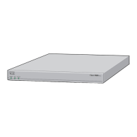
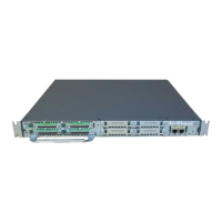
Figure1-2 below shows a router of 2 RU height with:
• A WIC in each WIC slot (containing interfaces Serial 0/0 and Serial 0/1 in physical slot W0,
interface Serial 0/2 in physical slot W1, and interface BRI 0/0 in physical slot W2)
• A 2-port T1 network module in slot1 (containing the following ports: T1 1/0 and T1 1/1)
• Two built-in Ethernet 10/100 interfaces—FastEthernet 0/0 and FastEthernet 0/1
Figure1-2 Example of a 2RU Router
Note The slot number for all WIC interfaces is always 0. (The W0 and W1 slot designations are for physical
slot identification only.) Interfaces in the WICs are numbered from right to left, starting with 0/0 for each
interface type, regardless of which physical slot the WICs are installed in. Some examples are: