7-15
Cisco TelePresence System 3200
OL-14521-01
Chapter 7 Building the Second Row Table Assembly
Parts List
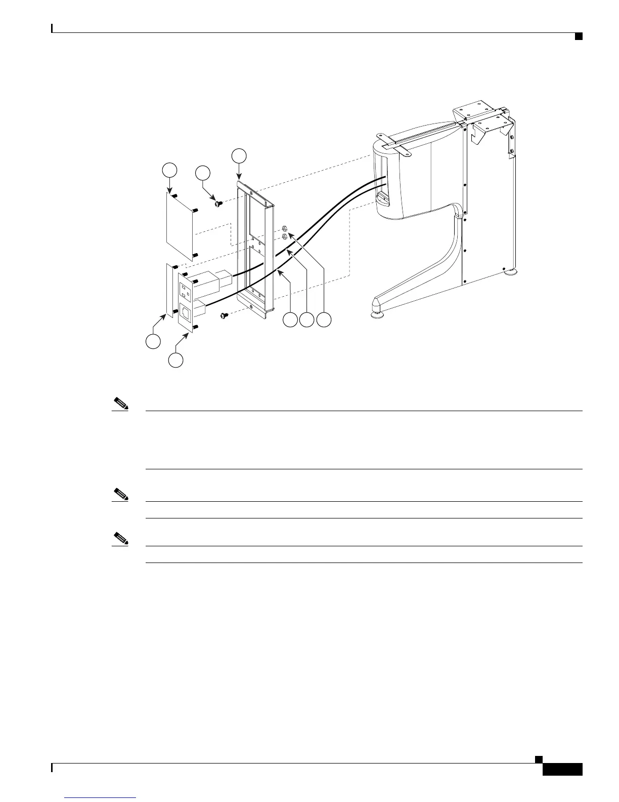
Figure 7-11 Foam Bumper Assembly
Step 12 Assemble the I/O modules for the inner molded foam bumpers.
Note The Ethernet cables are of different lengths. Attach the Ethernet cables to the I/O modules as follows:
• Use the 12M cable, 37-0965-01, for the I/O modules between sections 6 and 5
• Use the 3M cable, 37-0887-02, for the I/O modules between sections 5 and 7
Note Steps for routing the Ethernet and power cables are in Chapter 9, “Routing Power and Signal Cables.”
Note The flange on the I/O module cover piece is wider on the bottom than on the top.
204179
43
46
44
45
50
47 48 49