15-5
Cisco 7600 Series Router Cisco IOS Software Configuration Guide—12.1E
78-14064-04
Chapter 15 Configuring STP and IEEE 802.1s MST
Understanding How STP Works
The STP root bridge is the logical center of the spanning tree topology in a Layer 2 network. All paths
that are not needed to reach the root bridge from anywhere in the Layer 2 network are placed in STP
blocking mode.
BPDUs contain information about the transmitting bridge and its ports, including bridge and MAC
addresses, bridge priority, port priority, and path cost. STP uses this information to elect the root bridge
for the Layer 2 network, to elect the root port leading to the root bridge, and to determine the designated
port for each Layer 2 segment.
STP Protocol Timers
Table 15-3 describes the STP protocol timers that affect STP performance.
Creating the Spanning Tree Topology
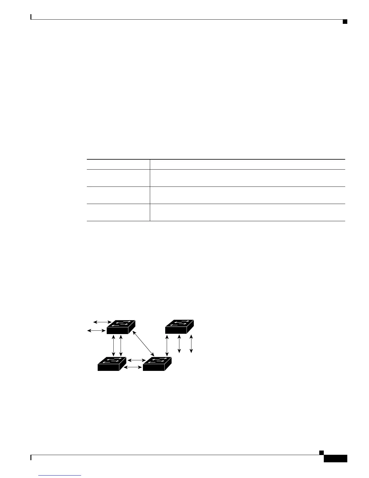
In Figure 15-1, Switch A is elected as the root bridge because the bridge priority of all the network
devices is set to the default (32768) and Switch A has the lowest MAC address. However, due to traffic
patterns, number of forwarding ports, or link types, Switch A might not be the ideal root bridge. By
increasing the priority (lowering the numerical value) of the ideal network device so that it becomes the
root bridge, you force an STP recalculation to form a new spanning tree topology with the ideal network
device as the root.
Figure 15-1 Spanning Tree Topology
When the spanning tree topology is calculated based on default parameters, the path between source and
destination end stations in a switched network might not be ideal. For instance, connecting higher-speed
links to a port that has a higher number than the current root port can cause a root-port change. The goal
is to make the fastest link the root port.
Table 15-3 STP Protocol Timers
Variable Description
Hello timer Determines how often the network device broadcasts hello messages to other
network devices.
Forward delay timer Determines how long each of the listening and learning states last before the
port begins forwarding.
Maximum age timer Determines the amount of time protocol information received on an port is
stored by the network device.
S5688
DP
DP
RP DP
DP
RP
DP
RP = Root Port
DP = Designated Port
DP
RP
DP
DA
CB