17-3
Cisco 7600 Series Router Cisco IOS Software Configuration Guide—12.1E
78-14064-04
Chapter 17 Configuring IP Unicast Layer 3 Switching on Supervisor Engine 2
Understanding How Layer 3 Switching Works
A received IP unicast packet is formatted (conceptually) as follows:
After the router rewrites an IP unicast packet, it is formatted (conceptually) as follows:
Hardware Layer 3 Switching Examples
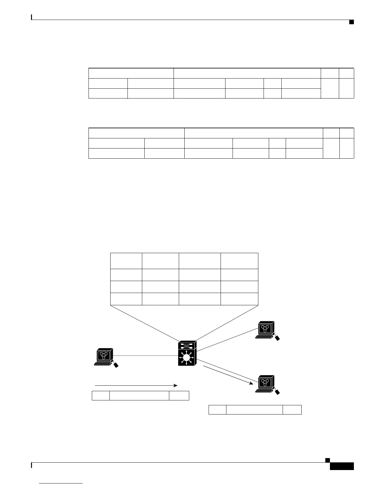
Figure 17-1 on page 17-3 shows a simple network topology. In this example, Host A is on the Sales
VLAN (IP subnet 171.59.1.0), Host B is on the Marketing VLAN (IP subnet 171.59.3.0), and Host C is
on the Engineering VLAN (IP subnet 171.59.2.0).
When Host A initiates an HTTP file transfer to Host C, Hardware Layer 3 switching uses the information
in the local forwarding information base (FIB) and adjacency table to forward packets from Host A to
Host C.
Figure 17-1 Hardware Layer 3 Switching Example Topology
Layer 2 Frame Header Layer 3 IP Header Data FCS
Destination Source Destination Source TTL Checksum
MSFC2 MAC Source A MAC Destination B IP Source A IP n calculation1
Layer 2 Frame Header Layer 3 IP Header Data FCS
Destination Source Destination Source TTL Checksum
Destination B MAC MSFC2 MAC Destination B IP Source A IP n-1 calculation2
Source IP
Address
171.59.1.2
171.59.1.2
Host A
171.59.1.2
Host B
171.59.3.1
Host C
171.59.2.2
171.59.2.2
171.59.1.2:171.59.2.2Data
171.59.3.1
171.59.2.2
171.59.1.2
Dd:Bb
Dd:Cc
Dd:Aa
Marketing
Engineering
Sales
Destination
IP Address
Rewrite Src/Dst
MAC Address
Destination
VLAN
MSFC
Subnet 1/Sales
MAC = Aa
MAC = Dd
MAC = Bb
MAC = Cc
Subnet 3/Marketing
Subnet 2/Engineering
Aa:Dd
171.59.1.2:171.59.2.2Data Dd:Cc
44610