3-23
Cisco Aironet 1250 Series Access Point Hardware Installation Guide
OL-8247-03
Chapter 3 Troubleshooting 1250 Series Autonomous Access Points
Connecting to the Access Point Locally
Follow these steps to open the CLI by connecting to the access point console port:
Step 1 Connect a nine-pin, female DB-9 to RJ-45 serial cable to the RJ-45 console port on the access point and
to the COM port on a computer.
Tip Bend the RJ-45 connector end of the cable approximately 90 degrees before attempting to
connect to the access point console port.
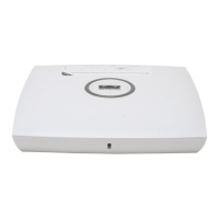
Figure 3-4 shows the console port and MODE button locations.
Figure 3-4 Console Port and MODE Button Locations
Note The Cisco part number for the DB-9 to RJ-45 serial cable is AIR-CONCAB1200. Browse to
http://www.cisco.com/go/marketplace to order a serial cable.
Step 2 Set up a terminal emulator on your PC to communicate with the access point. Use the following settings
for the terminal emulator connection: 9600 baud, 8 data bits, no parity, 1 stop bit, and no flow control.
Step 3 At the prompt, enter the administrator username and password. The default username is Cisco and the
default password is Cisco. The username and password are case sensitive.
1 DC power connector (56 VDC) 3 Console port (RJ-45)
2 Ethernet port connector (RJ-45) 4 MODE button
230554
ETHERNET CONSOLE MODE+56VDC
1 2 3 4
CAUTION
EXTERNAL DC AND INLINE PoE
POWER SOURCE REQUIREMENTS
DETERMINED BY INSTALLED
RADIO MODULES
REFER TO
PRODUCT DOCUMENTATION
 Loading...