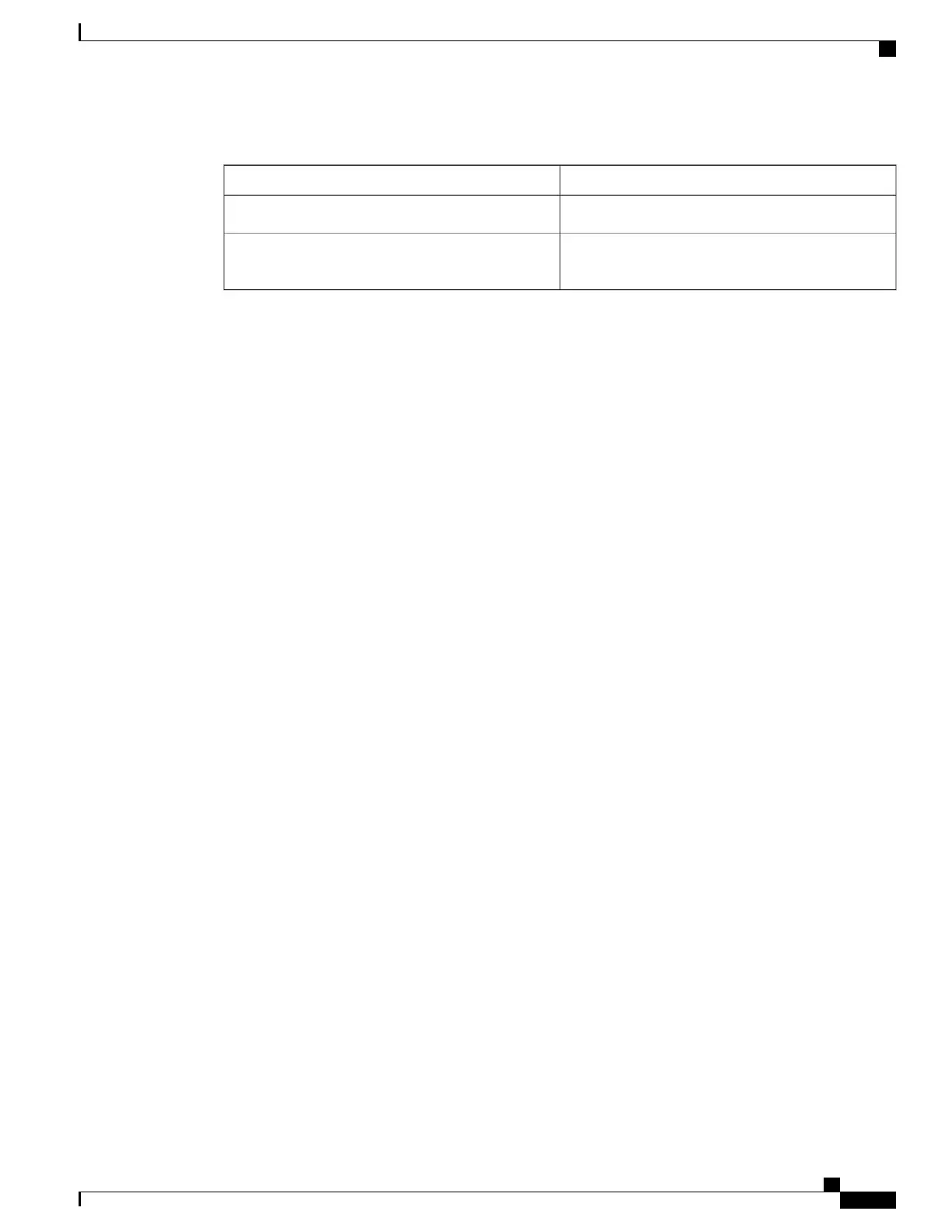
Table 14: Troubleshooting a Q
Command to View ContentsDatabase
show ip routeRouting Information Base
show mpls forwarding-table detailLabel Information Base and MPLS Forwarding
Information Base
The following example shows a ping mpls command where the MPLS echo request is not transmitted, as
shown by the returned Qs:
Device# ping mpls ipv4 10.0.0.1/32
Sending 5, 100-byte MPLS Echos to 10.0.0.1/32,
timeout is 2 seconds, send interval is 0 msec:
Codes: '!' - success, 'Q' - request not transmitted,
'.' - timeout, 'U' - unreachable,
'R' - downstream router but not target
Type escape sequence to abort.
QQQQQ
Success rate is 0 percent (0/5)
A show mpls forwarding-table command and a show ip route command demonstrate that the address is
not in either routing table:
Device# show mpls forwarding-table 10.0.0.1
Local Outgoing Prefix Bytes tag Outgoing Next Hop
tag tag or VC or Tunnel Id switched interface
Device# show ip route 10.0.0.1
% Subnet not in table
The MPLS echo request is not transmitted because the IPv4 address (10.0.0.1) is not found in either the LFIB
or the RIB routing table.
Load Balancing for IPv4 LDP LSPs
An Internet Control Message Protocol (ICMP) ping or trace follows one path from the originating device to
the target device. Round robin load balancing of IP packets from a source device is used to discover the various
output paths to the target IP address.
For MPLS LSP Ping and Traceroute, Cisco devices use the source and destination addresses in the IP header
for load balancing when multiple paths exist through the network to a target device. The Cisco implementation
of MPLS might check the destination address of an IP payload to accomplish load balancing (this checking
depends on the platform).
To check for load balancing paths, you use the 127.z.y.x /8 destination address in the ping mpls ipvr ip-address
address-mask destination address-start address-end address-increment command. The following examples
show that different paths are followed to the same destination. This demonstrates that load balancing occurs
between the originating device and the target device.
To ensure that the Fast Ethernet interface 1/0/0 on the PE1 device is operational, you enter the following
commands on the PE1 device:
Device# configure terminal
Enter configuration commands, one per line. End with CNTL/Z.
Device(config)# interface fastethernet 1/0/0
MPLS Basic Configuration Guide, Cisco IOS XE Everest 16.5.1 (Cisco ASR 900 Series)
95
MPLS LSP Ping, Traceroute, and AToM VCCV
Load Balancing for IPv4 LDP LSPs
 Loading...


