EasyManuals Logo

Cisco ASR 9010 Overview And Reference Guide

Cisco ASR 9010
170 pages
To Next Page IconTo Next Page
To Previous Page IconTo Previous Page
Page #127 background imageLoading...
Page #127 background image
2-73
Cisco ASR 9000 Series Aggregation Services Router Overview and Reference Guide
OL-17501-09
Chapter 2 Functional Description
Cooling System Functional Description
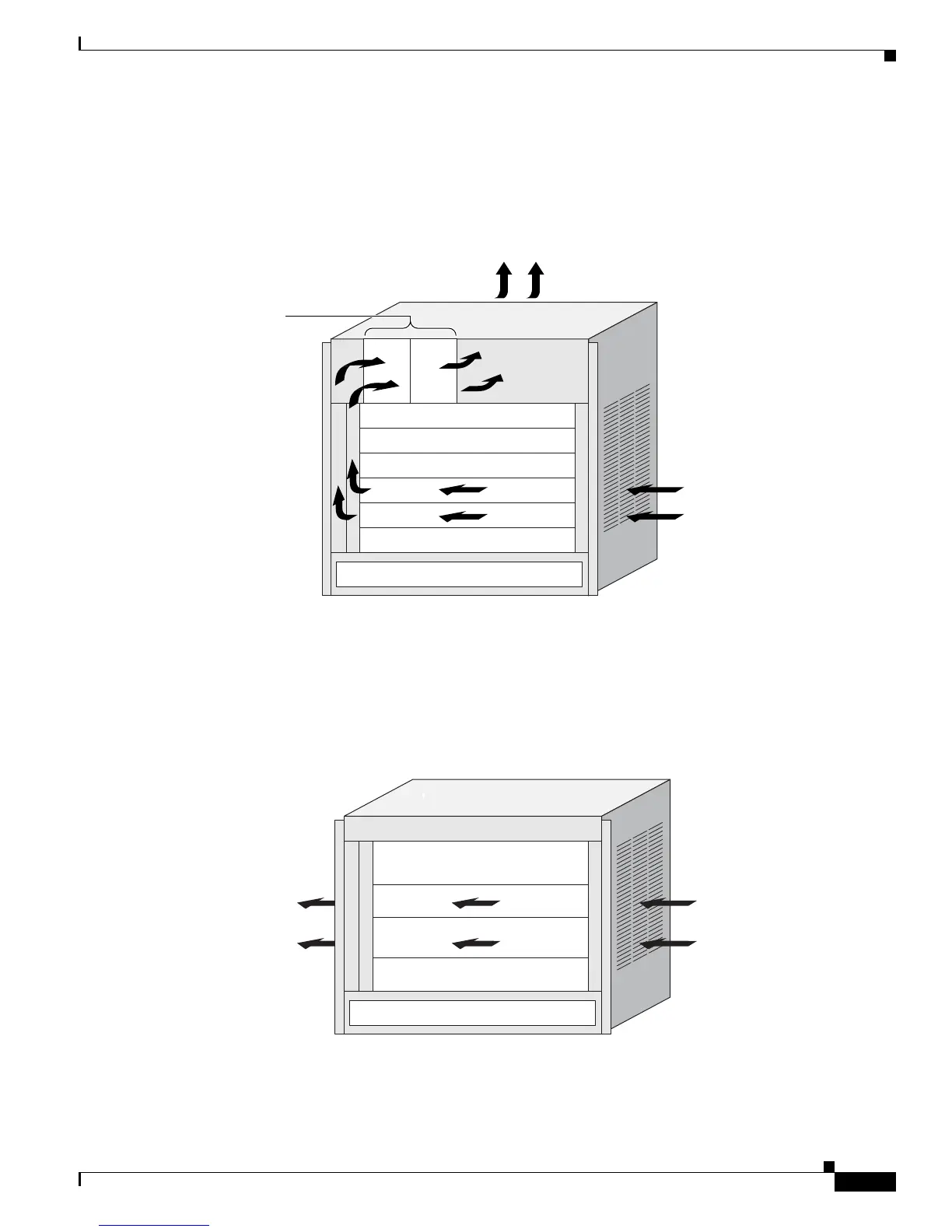
The Cisco ASR 9006 Router chassis has a side-to-top to rear cooling path. The inlet is at the right side
of the chassis, and the exhaust is at the upper rear.
Figure 2-65 shows the cooling path of the Cisco ASR 9006 Router chassis.
Figure 2-65 Cisco ASR 9006 Router Chassis Cooling Path
The Cisco ASR 9904 Router has a side-to-side cooling path. The inlet is at the right side of the cage, and
the exhaust is at the left side.
Figure 2-66 shows the cooling path of the Cisco ASR 9904 Router chassis.
Figure 2-66 Cisco ASR 9904 Router Chassis Cooling Path
243379
Air exhaust
RSPs and line cards
Room air
Power modules
Fan trays
351295
Room air
Air exhaust
RSPs and line cards
Power modules

Table of Contents

Other manuals for Cisco ASR 9010

Questions and Answers:

Question and Answer IconNeed help?

Do you have a question about the Cisco ASR 9010 and is the answer not in the manual?

Cisco ASR 9010 Specifications

General IconGeneral
ChassisModular
Rack Units21 RU
Operating SystemCisco IOS XR
Form FactorRack-mountable
Number of Slots10
Power SupplyAC or DC
RedundancyYes
Slots8 line card slots, 2 route switch processor slots
Memory16 GB DRAM
Storage64 GB SSD (Route Processor)
Port TypesEthernet, OTN
Redundancy FeaturesRoute Processor, Power Supply, Fan Tray
Operating Temperature32 to 104°F (0 to 40°C)
Humidity5% to 90% non-condensing
Route ProcessorCisco ASR 9000 Series Route Switch Processor

Related product manuals