EasyManuals Logo

Cisco ASR 9010 Overview And Reference Guide

Cisco ASR 9010
170 pages
To Next Page IconTo Next Page
To Previous Page IconTo Previous Page
Page #50 background imageLoading...
Page #50 background image
1-34
Cisco ASR 9000 Series Aggregation Services Router Overview and Reference Guide
OL-17501-09
Chapter 1 Overview and Physical Description
Power System
AC and DC Power Modules
Each AC or DC power tray houses up to four power modules.
The AC and DC power trays in the Cisco ASR 9006 Router and Cisco ASR 9904 Router provide
N+1 redundancy.
The AC power trays in the Cisco ASR 9010 Router, Cisco ASR 9922 Router, and Cisco ASR 9912
Router provide N+N redundancy. The DC power trays provide N+1 redundancy.
The power trays drive a single output bus that delivers –54 V to all cards and fan trays that are plugged
into the backplane.
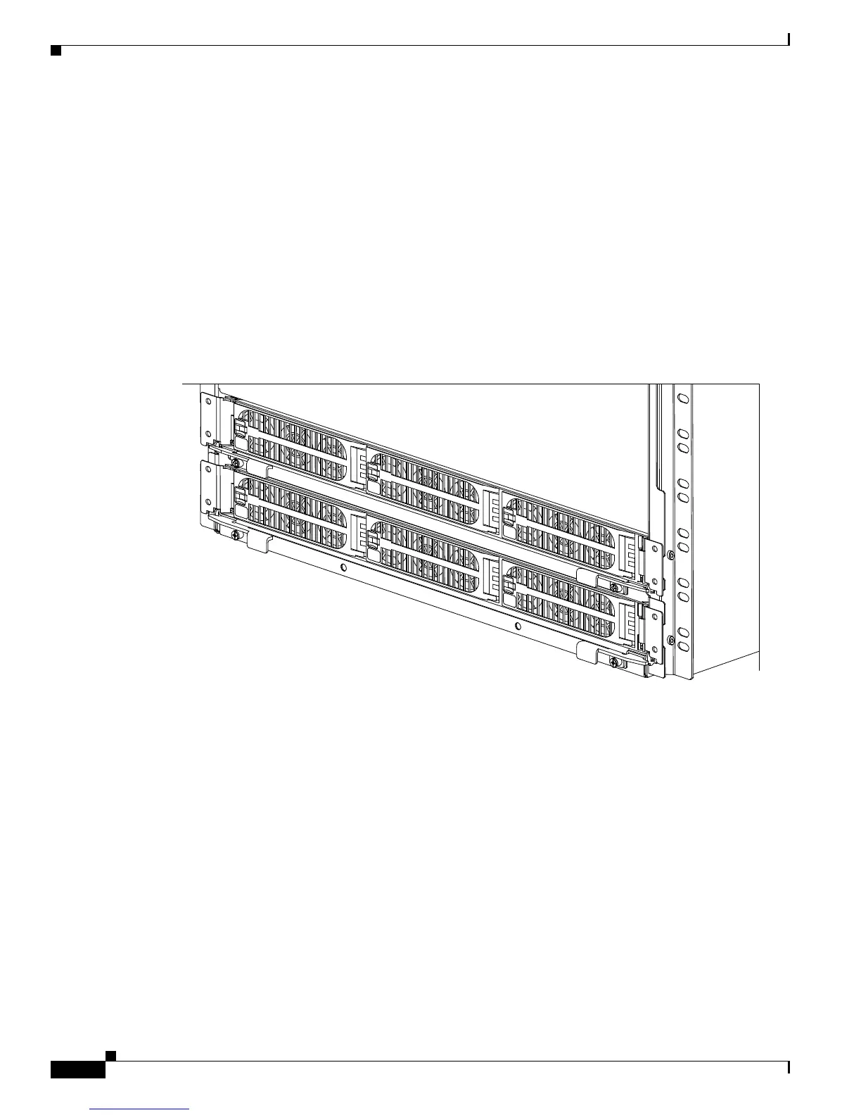
Figure 1-29 shows a front view of six version 1 power modules in the Cisco ASR 9010 Router.
Figure 1-29 Front System View of Power Trays—Cisco ASR 9010 Router with Version 1 Power
Tr a y s
242900

Table of Contents

Other manuals for Cisco ASR 9010

Questions and Answers:

Question and Answer IconNeed help?

Do you have a question about the Cisco ASR 9010 and is the answer not in the manual?

Cisco ASR 9010 Specifications

General IconGeneral
ChassisModular
Rack Units21 RU
Operating SystemCisco IOS XR
Form FactorRack-mountable
Number of Slots10
Power SupplyAC or DC
RedundancyYes
Slots8 line card slots, 2 route switch processor slots
Memory16 GB DRAM
Storage64 GB SSD (Route Processor)
Port TypesEthernet, OTN
Redundancy FeaturesRoute Processor, Power Supply, Fan Tray
Operating Temperature32 to 104°F (0 to 40°C)
Humidity5% to 90% non-condensing
Route ProcessorCisco ASR 9000 Series Route Switch Processor

Related product manuals