Network timing interfaces support redundancy in a redundant RSP configuration. Network timing interfaces
on a redundant RSP remain in operation while the RSP is in hot standby mode.
RSP Interfaces
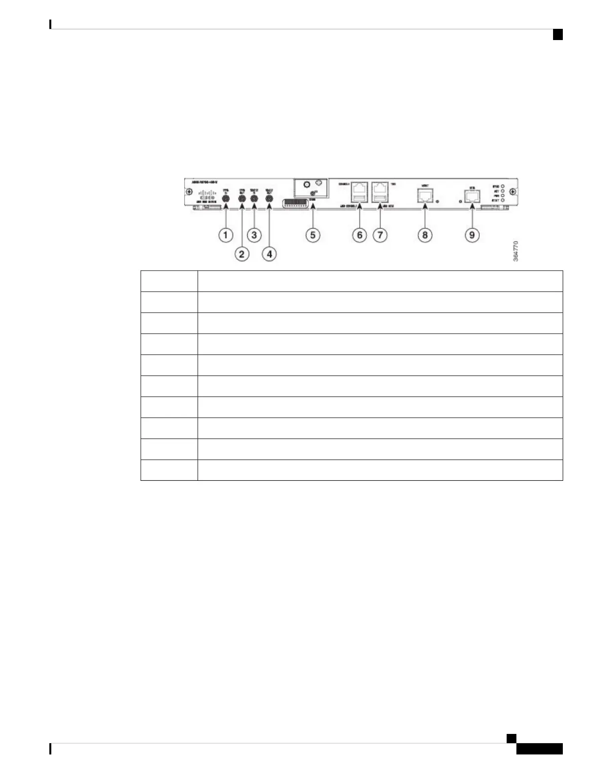
The figure below summarizes the interfaces on the RSP module.
Figure 2: RSP Interfaces Summary
InterfaceLabel
1 PPS input timing port1
1 PPS output timing port2
10 MHz input timing port3
10 MHz output timing port4
GNSS RF IN (SMA Threaded Connector)5
USB console port6
USB memory port7
Ethernet management port8
BITS timing port9
Interface Modules
The network interfaces are provided through pluggable interface modules.
The following list describes the various IM port density:
• GE SFP ports—Supports 100/1000 modes
• GE Copper RJ45 ports—Supports 10/100/1000 operation
• 10GE SFP+ or XFP ports—Supports 10G mode in Phase2 IMs
• 10GE port on Phase2 IMs—Supports LAN, WAN, OTU1e/2/2e modes of operation
• 2X40 GE interface module—Supports QSFP mode
• T1/E1 ports with integrated inter-office surge protection—Supports TDM channelized, PWE3 processing
and ATM IMA bundles
Cisco ASR 907 Router Hardware Installation Guide
13
Cisco ASR 907 Router Overview
RSP Interfaces