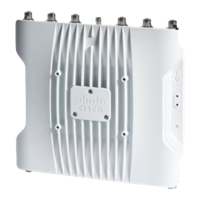
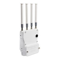
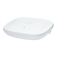
Table 3: Supported SFP Modules
Operating Temperature
Range
Fiber/CableDistancePID
INDMMF220-550mGLC-SX-MM-RGD=
INDMMF/SMF550m/10kmGLC-LX-SM-RGD=
INDCAT 5e100mGLC-T-RGD=
INDSMF10kmSFP-10G-LR10-I
EXTCAT 6A/CAT 730m@10GbpsSFP-10G-T-X
SFP modules are not hot-swappable. When you plug and unplug the SFP module, a manual reload of the AP
is required.
Note
Client data is passed to the network controller through the fiber connection via a fiber-capable switch or
controller. Configuration information can be found in the controller configuration guide of the switch or
controller you are using.
Antennas and Radios
The following sections provide detailed information about the AP's antennas and radios.
Internal Antennas and GNSS Receiver
The IW9167I access point has the following internal antennas:
• Four internal dual-band antennas with a dedicated 2.4 GHz radio and a 5 GHz radio
• Four internal antennas with a dedicated 6 GHz radio
• One internal single-band antenna with a dedicated 2.4 GHz IoT radio
• Two tri-band antennas with a dedicated 2.4 GHz, 5 GHz, and 6 GHz Aux radio
The IW9167I is equipped with a standard-precision GNSS receiver for geolocation, with L1/G1/E1/B1
frequencies supported: 1.559 – 1.610 GHz. For best GNSS performance, the AP should be mounted outdoors
with a clear view of the sky. Location accuracy may be affected if the antenna’s view is obstructed. The
following figure shows the GNSS windows on the bottom of the access point.
Cisco Catalyst IW9167I Heavy Duty Access Point Hardware Installation Guide
7
About Cisco Catalyst IW9167I Heavy Duty Access Point
Antennas and Radios

 Loading...
