Step 3 Connect a shielded outdoor-rated Ethernet (CAT5e or better) cable between the power injector and the AP's PoE-in
connector.
Step 4 Connect the Ethernet cable to the AP PoE-In port.
Connecting to the DC Power Port Using Cable Gland
Follow these steps to connect to the DC power port using cable gland:
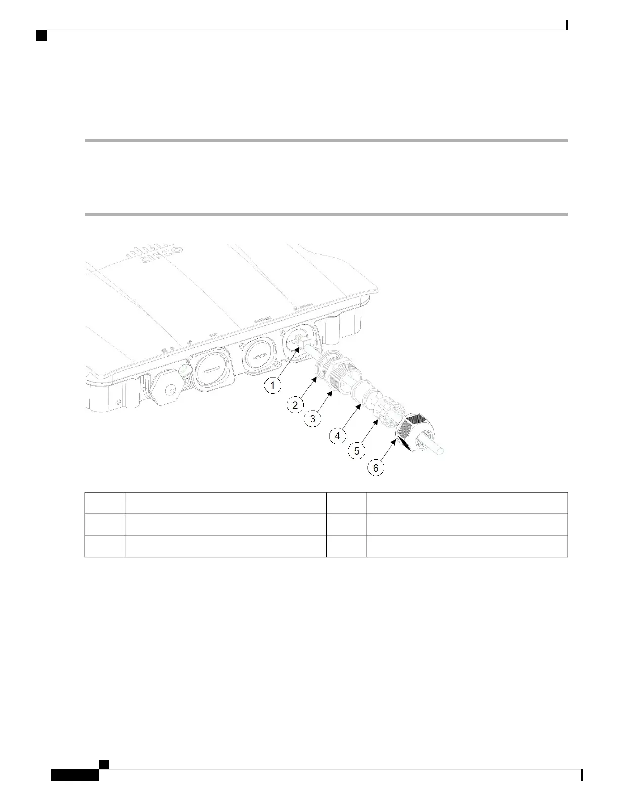
Step 1 Disassemble PG13 cable gland and slide parts over DC cable in the order shown in the following figure:
Grommet4DC cable1
Ferrule5Gasket2
Clamp nut6PG13 body3
Step 2 Plug 4P connector cable into the DC connector in the chassis.
Step 3 Thread the PG13 body (with gasket) into the chassis.
Step 4 Insert the grommet into the ferrule, and press it into the PG13 body.
Step 5 Tighten the clamp nut onto the PG13 body until the grommet compresses onto the DC cable.
Cisco Catalyst IW9167I Heavy Duty Access Point Hardware Installation Guide
36
Installation Overview
Connecting to the DC Power Port Using Cable Gland