Grommet4RJ45 cable1
Ferrule5Gasket2
Clamp nut6PG13 body3
Step 2 Plug the RJ45 cable into the RJ45 connector in the chassis.
Step 3 Thread the PG13 body (with gasket) into the chassis. The PG13 must be screwed into the chassis at this point.
Step 4 Insert the grommet into the ferrule, and press it into the PG13 body.
Step 5 Tighten the clamp nut onto the PG13 body until the grommet compresses onto the RJ45 cable.
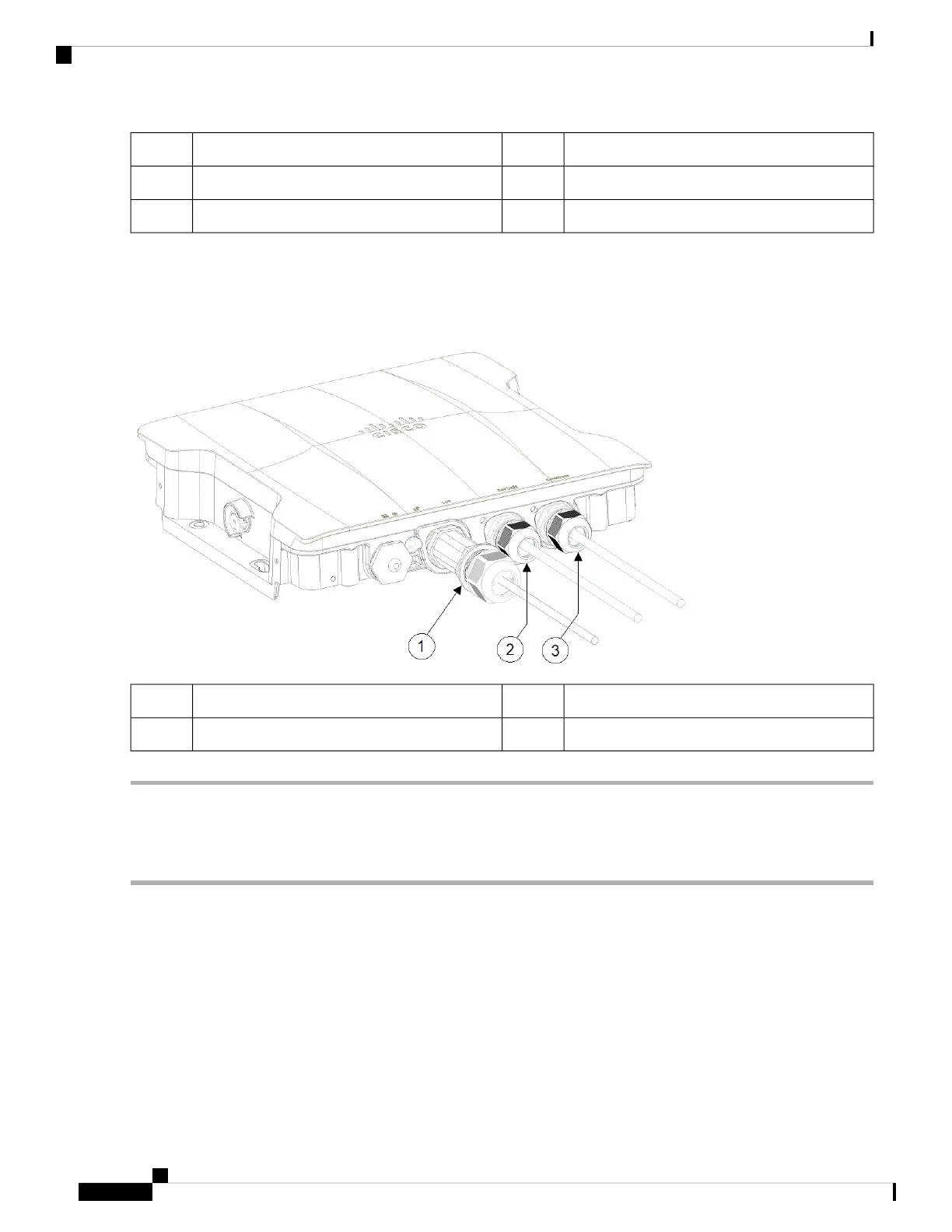
DC power port connected using cable gland3SFP port connected using cable gland1
RJ45 port connected using cable gland2
Connecting to the RJ45 Port Using M12 Adapter
Follow these steps to connect to the RJ45 port using M12 adapter:
Step 1 Ensure the O-ring is on the M12 adapter.
Cisco Catalyst IW9167I Heavy Duty Access Point Hardware Installation Guide
40
Installation Overview
Connecting to the RJ45 Port Using M12 Adapter