1-8
Cisco CGS 2520 Hardware Installation Guide
OL-31444-01
Chapter 1 Product Overview
LEDs
Management Ports
You can connect the switch to a PC running Microsoft Windows or to a terminal server through either
the RJ-45 console port or the USB console port.
• RJ-45 console port. The RJ-45 connection uses an RJ-45-to-DB-9 female cable
• USB mini-Type B console port (5-pin connector); the USB connection uses a USB Type A-to-5-pin
mini-Type B cable
The USB console interface speeds are the same as the RJ-45 console interface speeds.
To use the USB console port, you must install the Cisco Windows USB device driver on the device that
is connected to the USB console port (device running with Microsoft Windows).
Note For information about downloading the Cisco USB device driver, see the “Installing the Cisco Microsoft
Windows USB Device Drivers” section on page C-4.
With the Cisco Windows USB device driver, connecting and disconnecting the USB cable from the
console port does not affect Windows HyperTerminal operations. Mac OS X or Linux require no special
drivers.
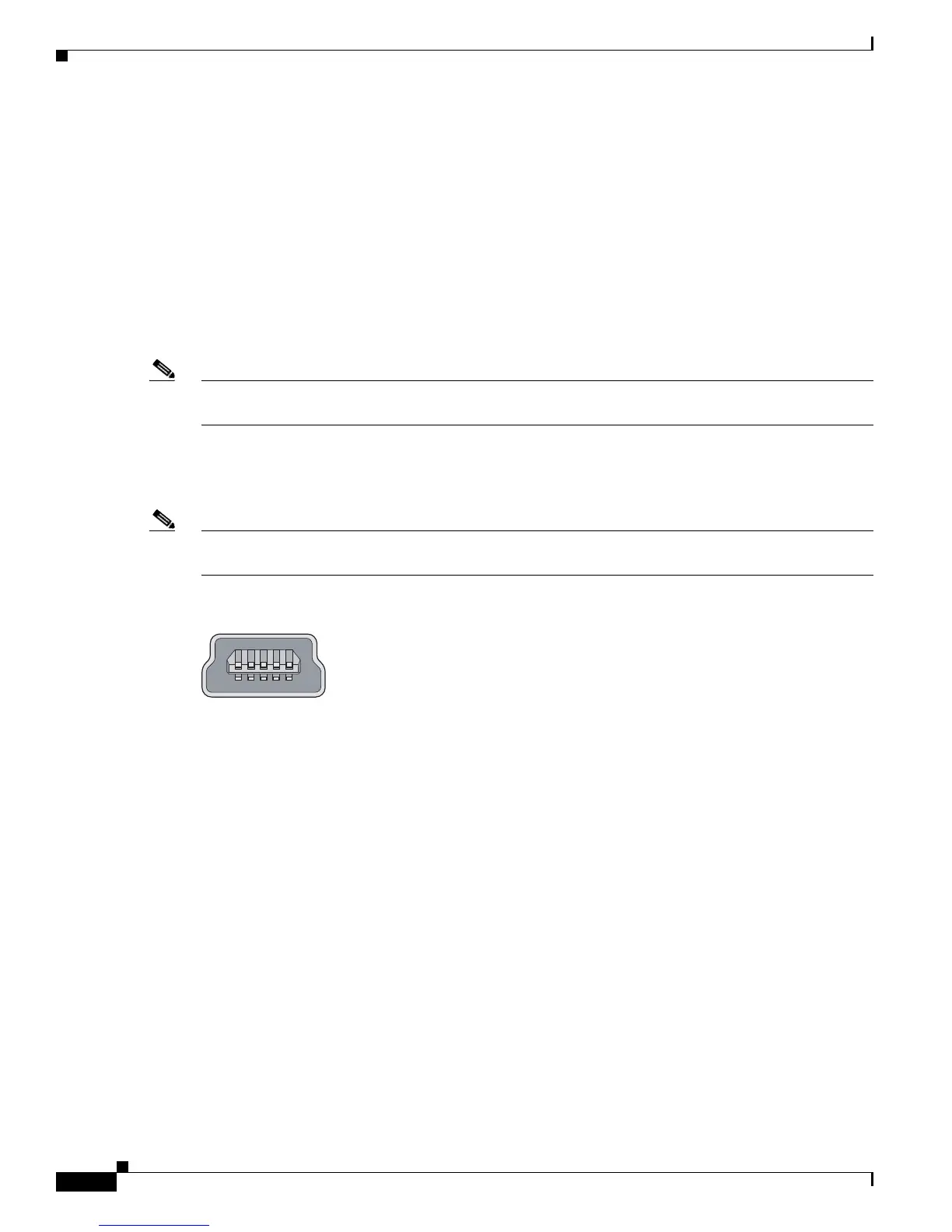
Note The 5-pin mini-Type B connectors resemble the 4-pin mini-Type B connectors. They are not compatible.
Use only the 5-pin mini-Type B. See Figure 1-5.
Figure 1-5 USB Mini-Type B Port
The configurable inactivity timeout reactivates the RJ-45 console port if the USB console port is
activated, but no input activity occurs on it for a specified time period. When the USB console port
deactivates due to a timeout, you can restore its operation by disconnecting and reconnecting the USB
cable. For information on using the CLI to configure the USB console interface, see the switch software
guide.
LEDs
You can use the switch system and port LEDs to monitor switch activity and performance.
The information in this section includes:
• Switch Panel LEDs, page 1-9
• System LED, page 1-9
• Power Supply Module LEDs, page 1-10
• Alarm LEDs, page 1-10
• Console LEDs, page 1-10
• Port LEDs, page 1-11
• Dual-Purpose Port LEDs, page 1-12
253163