1-14
Cisco CGS 2520 Hardware Installation Guide
OL-31444-01
Chapter 1 Product Overview
Power Supply Side
Power Supply-Side LEDs
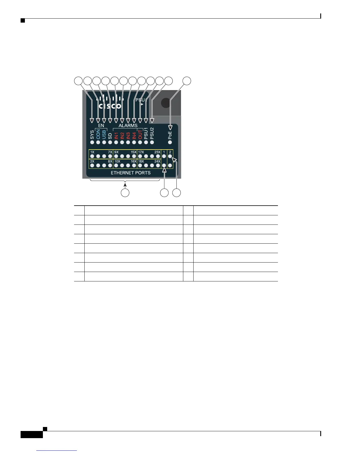
Figure 1-9 Switch LEDs
Power Supply Features
The switch has two slots for power supply modules:
• PWR-RGD-LOW-DC: low-voltage DC (for voltage information, see Table A-8)
• PWR-RGD-AC-DC: high-voltage AC or DC (for voltage information, see Table A-7)
• PWR-RGD-AC-DC-C: high-voltage AC or DC for China
The switch supports these power supply module combinations:
• Single low-voltage DC
• Single high-voltage AC or DC
• Two high-voltage AC or DC
1 SYS (system) 9 OUT (alarm output)
2 CON (console) 10 PSU1 (power supply 1)
3 USB LED 11 PSU2 (power supply 2)
4 SD (SD flash memory card) 12 PoE
1
1. Only on the Cisco CGS-2520-16S-8PC switch.
For a description of the LEDs, see LEDs, page 1-8.
5 IN1 (alarm input 1) 13 Express setup button
6 IN2 (alarm input 2) 14 Ethernet port
7 IN3 (alarm input 3) 15 10/100/1000 port
8 IN4 (alarm input 4) 16 SFP port
Cisco Connected Grid
Switch 2500 Series
21 3 45678 9 10 11 12
207199
13 14
15
 Loading...