2-25
Cisco CGS 2520 Hardware Installation Guide
OL-31444-01
Chapter 2 Switch Installation
Connecting Devices to the Ethernet Ports
Connecting to the 10/100 and 10/100/1000 Ports
The 10/100 and 10/100/1000 Ethernet ports use standard RJ-45 connectors with Ethernet pinouts. The
maximum cable length is 328 feet (100 meters). The 100BASE-TX and 1000BASE-T traffic requires
Category 5, Category 5e, or Category 6 UTP cable. The 10BASE-T traffic uses Category 3 or Category
4 cable.
The auto-negotiation feature is enabled by default on the switch. At this setting, the switch ports
configure themselves to operate at the speed of the attached device. If the device does not support
auto-negotiation, you can set the switch port speed and duplex parameters. To maximize performance,
either let the ports autonegotiate both speed and duplex, or set the port speed and duplex parameters on
both ends of the connection.
For simplified cabling, the automatic medium-dependent interface crossover (auto-MDIX) feature is
enabled by default. With auto-MDIX enabled, the switch detects the required cable type for copper
Ethernet connections and configures the interface accordingly. Therefore, you can use either a crossover
or a straight-through cable for connections to a 10/100/1000 Ethernet port, regardless of the type of
connected device.
See the switch software configuration guide or the switch command reference on Cisco.com for more
information about auto-negotiation and auto-MDIX.
If auto-MDIX is disabled, use the guidelines in Table 2-1 to select the cable for connecting the
10/100/1000 Ethernet ports to other devices.
See the “Connector and Cable Specifications” section on page B-1 for cable-pinout descriptions.
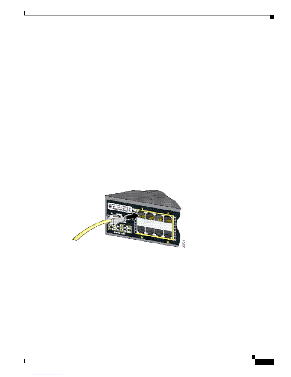
Figure 2-24 Connecting to an Ethernet Port
Connecting to the 10/100 PoE+ Ports
The Cisco CGS-2520-16S-8PC switch (and the CGS-2520-16S-8PC-C switch) 10/100 PoE+ ports have
the same auto-negotiation settings and cabling requirements as those in the “Connecting to the 10/100
and 10/100/1000 Ports” section on page 2-25. These ports provide PoE power.
See the “PoE and PoE+ Ports” section on page 1-4 for information on the cables and connectors.
The ports provide PoE support for devices compliant with IEEE 802.3af and also provide Cisco
prestandard PoE support for Cisco IP Phones and Cisco Aironet Access Points.
On a per-port basis, you can control whether or not a port automatically provides power to a connected
IP phone or an access point.
To access an advanced PoE+ planning tool, use the Cisco Power Calculator on Cisco.com:
http://tools.cisco.com/cpc/launch.jsp