B-2
Cisco CGS 2520 Hardware Installation Guide
OL-31444-01
Appendix B Connector and Cable Specifications
Connector Specifications
When connecting 10/100 ports to devices such as servers, workstations, and routers, you can use a two
or four twisted-pair straight-through cable wired for 10BASE-T and 100BASE-TX. Figure B-5 shows
the two twisted-pair straight-through cable schematics. Figure B-7 shows the four twisted-pair
straight-through cable schematics.
When connecting the ports to other devices, such as switches or repeaters, you can use a two or four
twisted-pair crossover cable. Figure B-6 shows the two twisted-pair crossover cable schematics.
Figure B-8 shows the four twisted-pair crossover cable schematics.
If auto-MDIX is disabled, use a straight-through cable to connect ports when only one port is labeled
with an X. Use a crossover cable to connect ports when both ports are labeled with an X or when both
ports are not labeled with an X.
You can use Category 3, 4, or 5 cabling when connecting to 10BASE-T-compatible devices. You must
use Category 5 (or higher) cabling when connecting to 100BASE-TX-compatible devices.
Note You can use the mdix auto interface configuration command in the CLI to enable the automatic
medium-dependent interface crossover (auto-MDIX) feature. When the auto-MDIX feature is enabled,
the switch detects the required cable type for copper Ethernet connections and configures the interfaces
accordingly. Therefore, you can use either a crossover or a straight-through cable for connections to a
copper 10/100, 10/100/1000, or 1000BASE-T SFP module port on the switch, regardless of the type of
device on the other end of the connection.
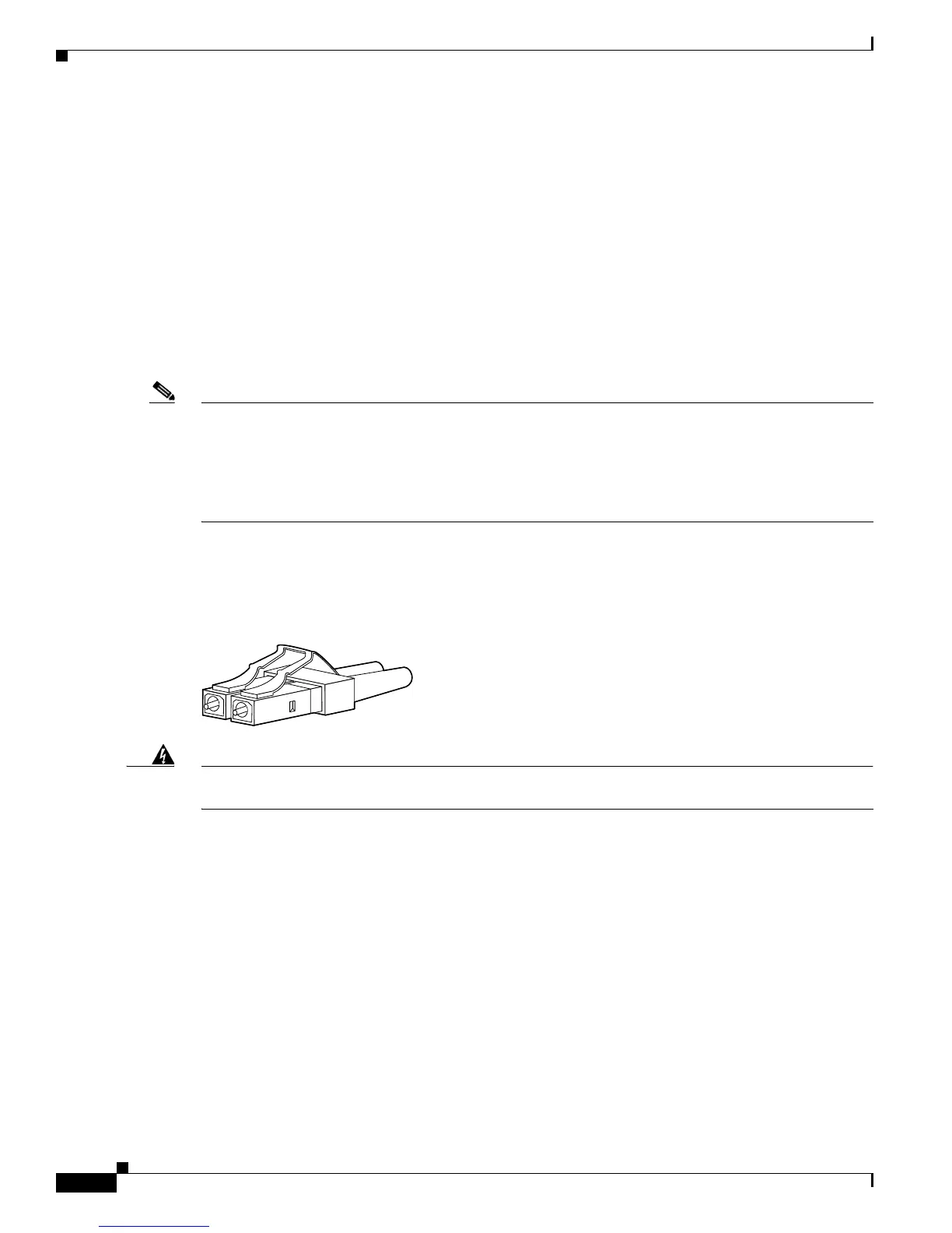
SFP Module Connectors
Figure B-2 Fiber-Optic SFP Module LC Connector
Warning
Invisible laser radiation may be emitted from disconnected fibers or connectors. Do not stare into
beams or view directly with optical instruments.
Statement 1051
 Loading...