3-5
Cisco CGS 2520 Hardware Installation Guide
OL-31444-01
Chapter 3 Power Supply Installation
Power Supply Module Installation
Follow these steps to install a dual-hole lug on the switch. Be sure to follow any grounding requirements
at your site.
Step 1 Use a Phillips screwdriver or a ratcheting torque screwdriver with a Phillips head to remove the ground
screw from the cable side of the switch. You need the screw in Step 4.
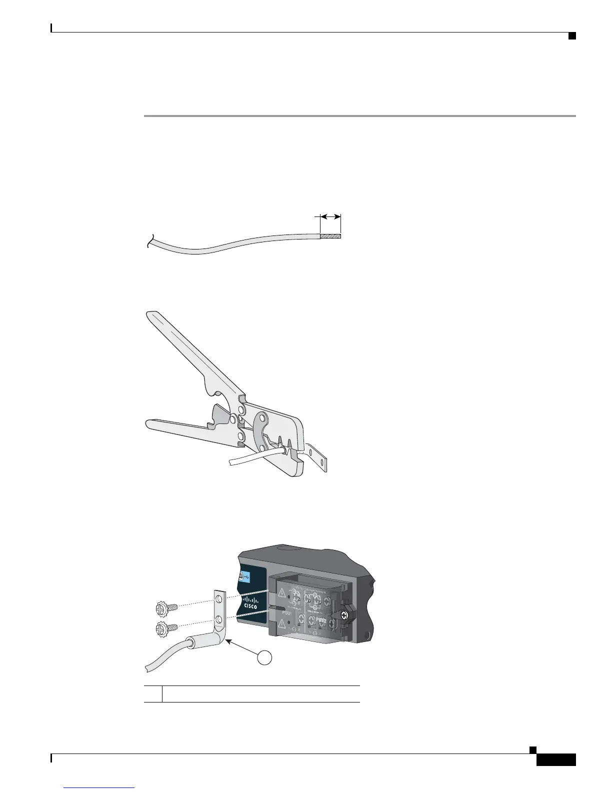
Step 2 Strip the 6-gauge ground wire to 0.5 inch (12.7 mm) ± 0.02 inch (0.5 mm) (see Figure 3-3). Stripping
more than the recommended amount of wire can leave exposed wire from the connector.
Figure 3-3 Stripping the Ground Wire
Step 3 Insert the ground wire into the terminal lug, and crimp the terminal to the wire (see Figure 3-4).
Figure 3-4 Crimping the Terminal Lug
Step 4
Slide the ground screw from Step 1 through the terminal lug. Insert the ground screws into the opening
on the cable side.
Figure 3-5 Attaching the Terminal Lug
0.25 in. (6.3 mm)
±
0.02 in. (0.5 mm)
60531
1 Dual-hole terminal lug
Cisco CGS 2520
1
207217