3-8
Cisco CGS 2520 Hardware Installation Guide
OL-31444-01
Chapter 3 Power Supply Installation
Power Supply Module Installation
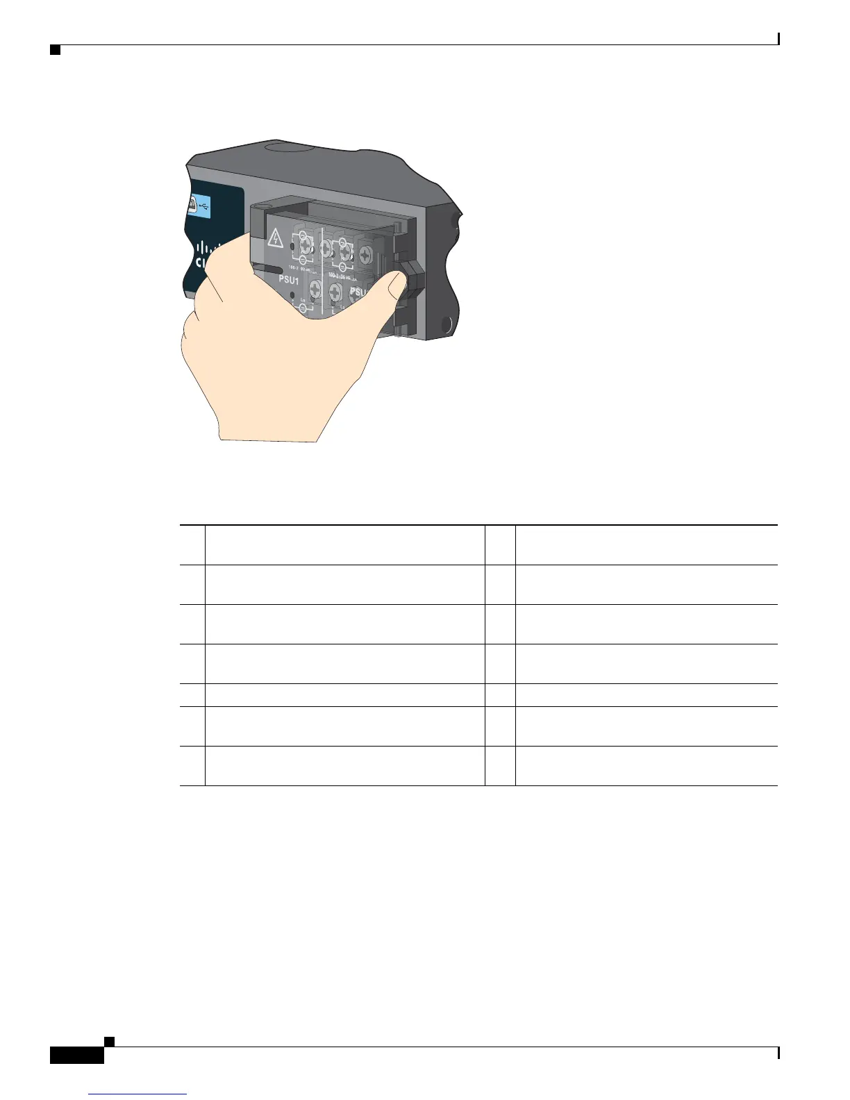
Figure 3-9 Opening the Power-Input Terminal Cover
The terminal screws labels are on the power-input terminal cover (see Figure 3-10).
Figure 3-10 Power-Input Terminal
Cisco CGS 2520
207426
100-240V~, 50-60Hz, 2A
100-240V~, 50-60Hz, 2A
5
2A
2A
10A
10A
5
1 Line connection for high-voltage AC (PSU1) 8 Line connection for high-voltage AC (for
PSU2)
2 Neutral connection for high-voltage AC
(PSU1)
9 Neutral connection for high-voltage AC
(PSU2)
3 Positive connection for high-voltage DC
(PSU1)
10 Positive connection for high-voltage DC
(PSU2)
4 Negative connection for high-voltage DC
(PSU1)
11 Negative connection for high-voltage DC
(PSU2)
5 PSU1 (power supply module 1) 12 PSU2 (power supply module 2)
6 Positive connection for low-voltage DC
(PSU1)
13 Positive connection for low-voltage DC
(PSU2)
7 Negative connection for low-voltage DC
(PSU1)
14 Negative connection for low-voltage DC
(PSU2)
 Loading...