3-10
Cisco CGS 2520 Hardware Installation Guide
OL-31444-01
Chapter 3 Power Supply Installation
Power Supply Module Installation
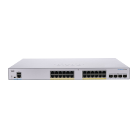
Figure 3-12 Crimping the Spade Terminal Lug
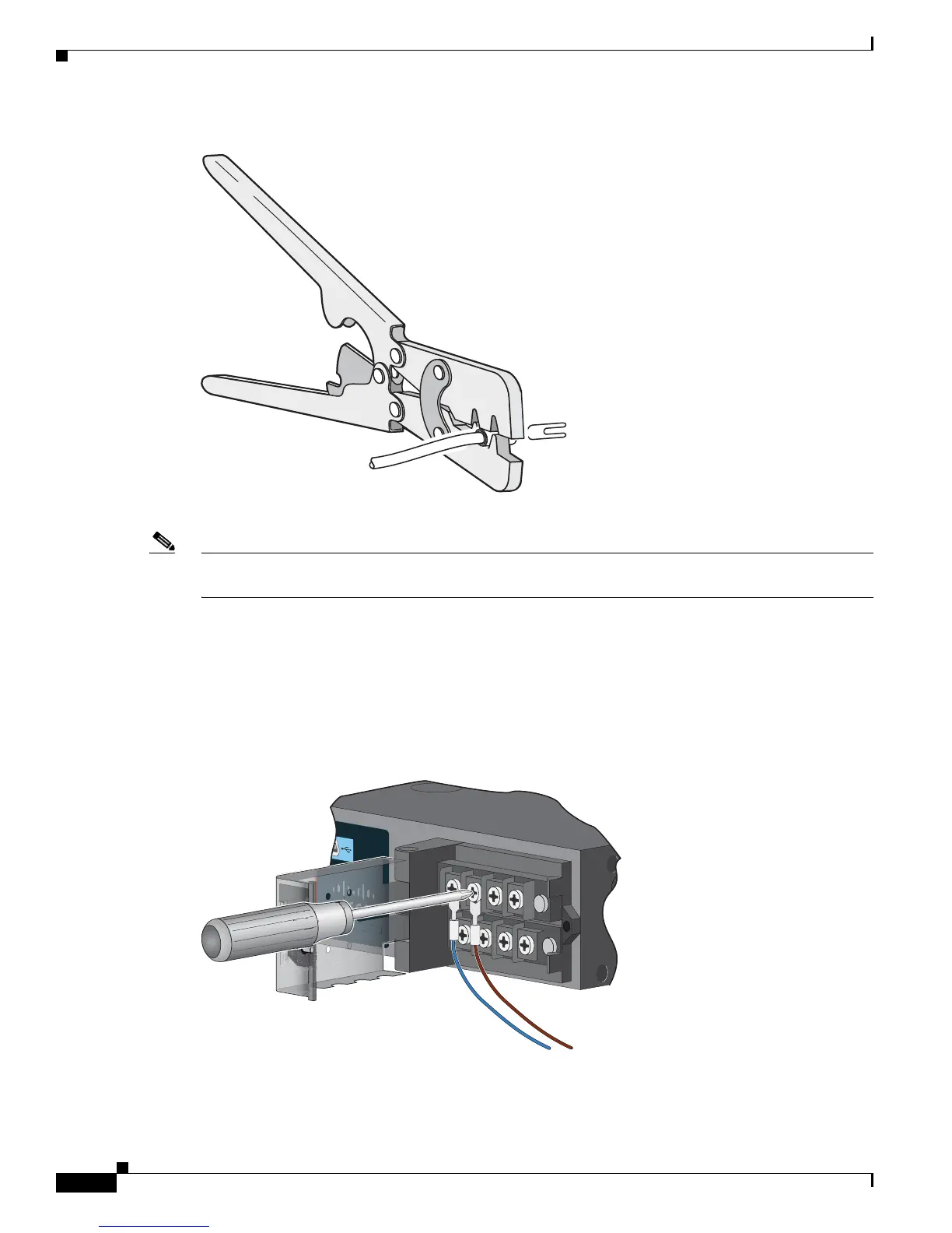
Step 6
Loosen the terminal screw, and slide the terminal under the screw and washer (see Figure 3-14).
Note Use the appropriate terminal screws, depending on whether you are installing a high-voltage (AC or DC)
or a low-voltage (DC) power supply.
Step 7 AC power connection
Connect the line wire into the terminal screw labeled L and the neutral wire into the terminal screw
labeled N.
Make sure that you cannot see any wire lead. Only wire with insulation should extend from the terminal
screw.
Figure 3-13 Connecting the Wires to the High-Voltage AC Power (PSU1)
DC power connection. Connect the positive wire into the terminal screw labeled +, and the negative wire
into the terminal screw labeled –. Make sure that you cannot see any wire lead. Only wire with insulation
should extend from the terminal screw.
100-240V~, 50-60Hz, 2.2A
100-240V~, 50-60Hz, 2.2A
207429
 Loading...