3-12
Cisco CGS 2520 Hardware Installation Guide
OL-31444-01
Chapter 3 Power Supply Installation
Removing the Power Supply Module
Step 1 We recommend that power be OFF at the AC or DC circuits. Locate the circuit breakers, turn them OFF
and tape them in the OFF position.
Note If the power is not off at the AC or DC circuit breaker, do not touch the power-input terminal.
Step 2 Verify that the PSU LED and PSU OK LED is blinking red or is off.
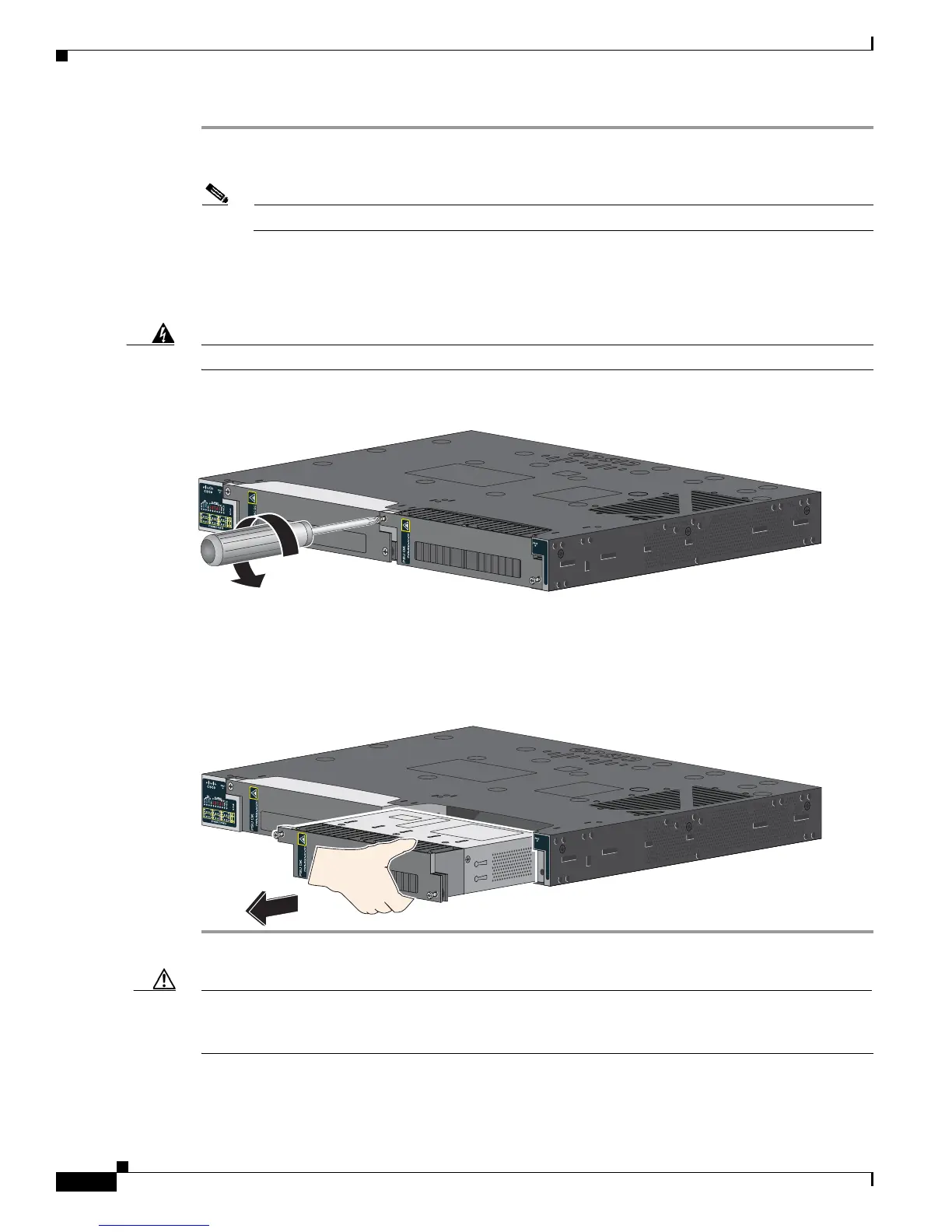
Step 3 Use a Phillips screwdriver to loosen the captive screws that secure the power supply module to the switch
(see Figure 3-15).
Warning
Hot surface.
Statement 1079
Figure 3-15 Removing the Screws
Step 4 Remove the power supply module from the power slot. The power supply module might be hot (see
Figure 3-16).
Step 5 Install a new power supply module or a blank cover.
Figure 3-16 Removing the Power Supply Module
Caution To prevent exposure to hazardous voltages and to contain electromagnetic interference (EMI), either a
power supply module or a blank cover must be in each power supply module slot at all times. You can
order the blank cover (part number RPS-CG-COVER=).
Cisco C onnected Grid
Sw itc h 2500 Series
207432
207433
Cisco C onnected Grid
Sw itc h 2500 Series
 Loading...