B-7
Cisco CGS 2520 Hardware Installation Guide
OL-31444-01
Appendix B Connector and Cable Specifications
Cables and Adapters
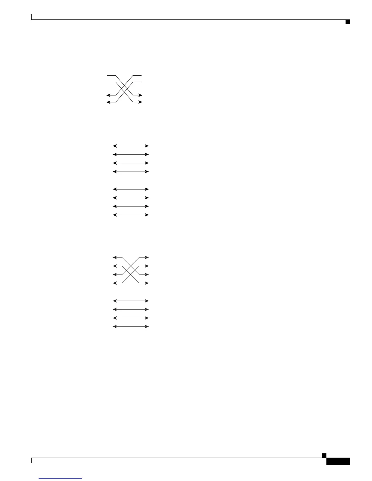
Figure B-6 Two Twisted-Pair Crossover Cable Schematic for 10/100 Ports
Figure B-7 Four Twisted-Pair Straight-Through Cable Schematic for 1000BASE-T Ports
Figure B-8 Four Twisted-Pair Crossover Cable Schematics for 1000BASE-T Ports
To identify a crossover cable, hold the cable ends side-by-side, with the tab at the back. The wire
connected to pin 1 on the left end should be the same color as the wire connected to pin 3 on the right
end. The wire connected to pin 2 on the left end should be the same color as the wire connected to pin 6
on the right end.
Switch
3 TD+
6 TD–
1 RD+
2 RD–
Switch
3 TD+
6 TD–
1 RD+
2 RD–
H5579
1 TP0+
2 TP0-
3 TP1+
6 TP1-
1 TP0+
2 TP0-
3 TP1+
6 TP1-
Switch Router or PC
4 TP2+
5 TP2-
7TP3+
8TP3-
4 TP2+
5 TP2-
7TP3+
8TP3-
65271
1 TP0+
2 TP0-
3 TP1+
6 TP1-
1 TP0+
Switch Switch
2 TP0-
3 TP1+
6 TP1-
4 TP2+
5 TP2-
7 TP3+
8 TP3-
4 TP2+
5 TP2-
7 TP3+
8 TP3-
65274
 Loading...