5-8 Cisco 4000 Series Hardware Installation and Maintenance
Memory Replacement Procedures
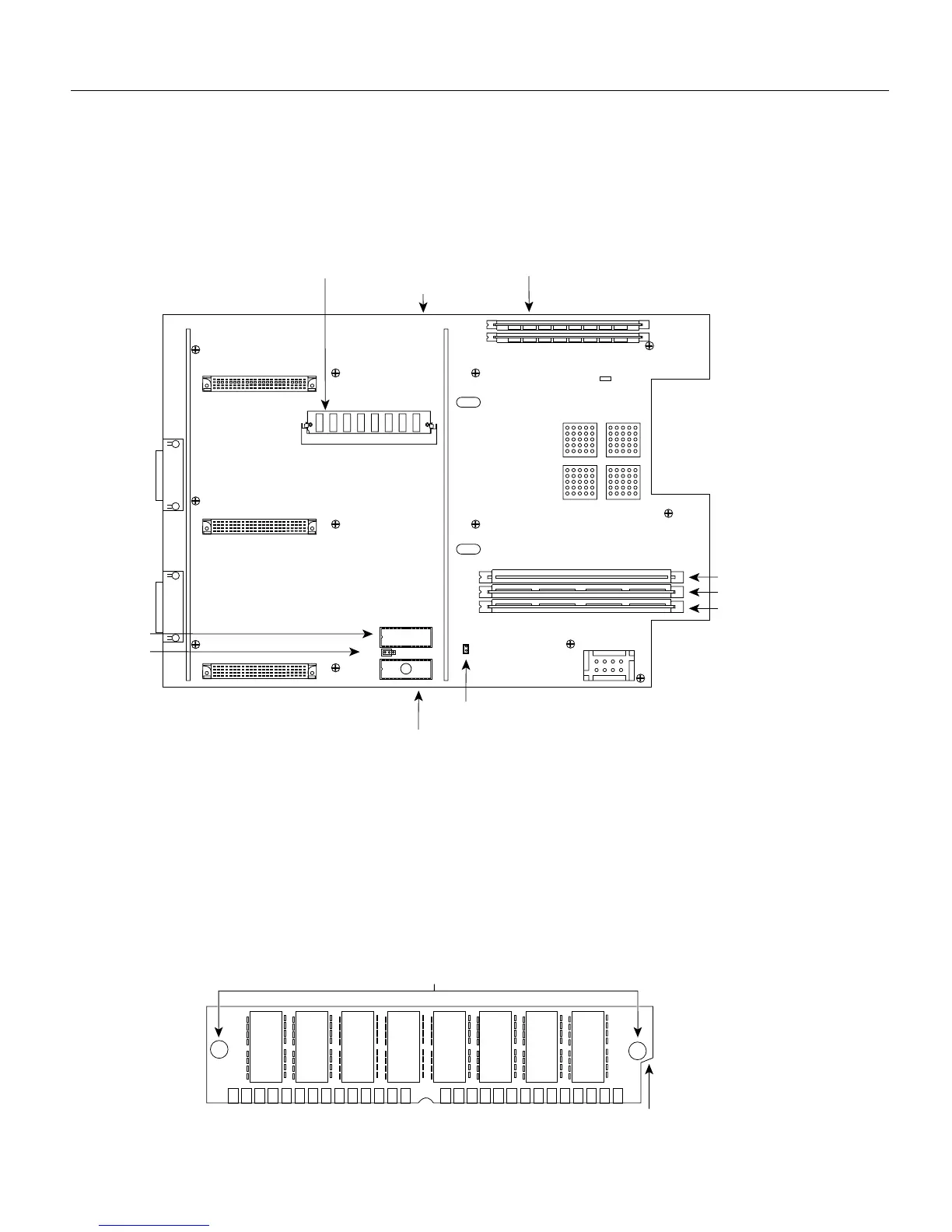
Figure 5-6 shows the Cisco 4500-M and Cisco 4700 SIMM and jumper locations.
Figure 5-6 Cisco 4500-M and Cisco 4700 SIMM Locations
Replacing Main Memory SIMMs
SIMMs are manufactured with a polarization notch to prevent them from being installed backward.
Figure 5-7 shows the polarization notch and locations of the alignment holes on a main memory
SIMM card. The main memory SIMM cards are installed with the connector edge down and the
component side facing in, as shown in the upper right of Figure 5-5 and Figure 5-6.
Figure 5-7 Cisco 4000 Series Main Memory SIMM
Main memory SIMM
sockets with correct
SIMM orientation
Front of chassis
Motherboard
Shared-memory
SIMM and socket
H2449
System Flash memory 1
J1
J6
System Flash memory 0
RxBoot Flash memory
Jumper in place enables
writing to Flash memory
Jumped pins
1 and 2
ROM monitor
U68
NVRAM
Alignment holes
Connector edge
Polarization notch
H2407