4-14 Cisco 4000 Series Hardware Installation and Maintenance
Reading Network Processor Module LED Indicators
ATM Network Processor Module LED Indicators
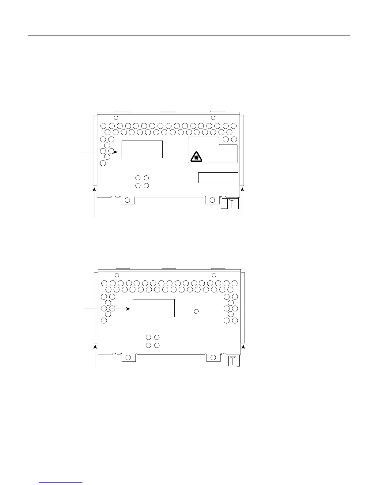
The three LEDs on the ATM network processor module are labeled loopback, local alarm, and
remote alarm. (See Figure 4-17 and Figure 4-18.)
Figure 4-17 ATM Network Processor Module with STS-3c/STM-1 Single Mode PLIM
Figure 4-18 ATM Network Processor Module with STS-3c/STM-1 Multimode PLIM
Four LEDs on the ATM front panel indicate the following:
• Busy—Not applicable in normal use
• Ready—When lit, configuration is complete and the module is ready for use
• Rx Cells—The module is receiving traffic (cells)
• Rx Alarm—Error condition: loss of signal or remote alarm
H3157
Alignment
groove
Alignment
groove
ATM
SM
XMTR RCVR
RX ALARM
AVOID EXPOSUREÐINVISIBLE
LASER RADIATION IS EMITTED
FROM THESE APERTURES.
WARNING
CISCO SYSTEMS, INC.
170 W. TASMAN DRIVE
SAN JOSE CA. 95134
DATE:
ÒComplies with FDA Radiation
Performance Standards, 21 CFR,
Subchapter JÓ
1300
NM
CLASS 1 LASER PRODUCT
LASERKLASSE 1
READY
RX CELLSBUSY